00191413-01.pdf - 第212页
6 Product / Package Form User Manu al Line Computer UNIX 6.1 Package Form Editor Software Version 501.xx 01/99 Issue 6 - 34 Fig. 6.1. 13 X- axis of the component is al igned with the long edge of the nozzle If the aforem…
User Manual Line Computer UNIX 6 Product / Package Form
Software Version 501.xx 01/99 Issue 6.1 Package Form Editor
6 - 33
6.1.3 Package Form Definition
6.1.3.1 Definition of the Component’s Coordinate System
NOTE
For the description of a component’s package form, the dimensions should, as a rule, be taken from the corre-
sponding data sheet. Please note, that the description always refers to a component as seen from above.
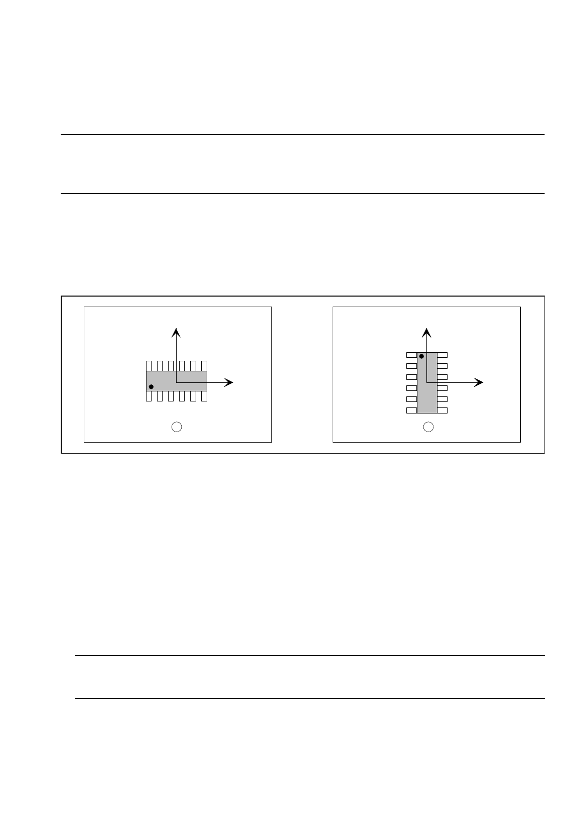
The component is displayed in its 0°-description in the view area of the Package Form Editor. Here, the origin
of the coordinate system is always located in the center of the view area. From there, the X-axis points to the
right, the Y-axis points upward. It is also possible to describe a component both in horizontal and in upright
position (see Fig. 6.1.12). As a rule, the center of the component coincides with the zero point of the coordinate
system.
Fig. 6.1.12 0°-Description in the Package Form Editor
Legend pertaining to Fig. 6.1.12:
➀
Correct (display in the view area)
➁
Incorrect (display in the view area)
The 0°-description of the standard package form contained in the package form library (GF-Bibliothek) is sub-
ject to certain rules which should also be observed for the creation of customer-specific package forms. It can
thus be ensured that different programmers can work with uniformly defined package forms. In this way it is
possible to determine, for example, the pick-up angle at the station without having to check the 0°-description
in the Package Form Editor.
An incorrect 0°-description may result in pick-up or vision errors at the station.
To avoid such errors, the following rule should be observed:
Rule: The long side of nozzles featuring rectangular suction areas is to be positioned along the
X-axis.
This means that die X-axis of the component points in the direction where the nozzle will make contact with the
long side of its suction area (see Fig. 6.1.13).
Exception: special nozzles with 90°-displacement
Y
X
Y
X
Y
X
1 2
6 Product / Package Form User Manual Line Computer UNIX
6.1 Package Form Editor Software Version 501.xx 01/99 Issue
6 - 34
Fig. 6.1.13 X-axis of the component is aligned with the long edge of the nozzle
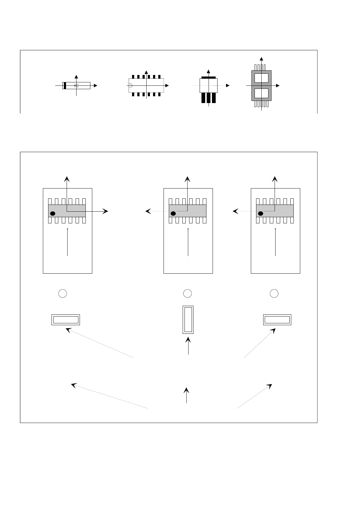
If the aforementioned rule is not observed, it may happen that the incorrect 0°-description will result in the errors
depicted below (see Fig. 6.1.14).
Fig. 6.1.14 0°-Description Errors
Y
X
Y
X
Y
X
Y
X
Y
X
Y
X
Y
X
0° 90° 0°
1 2 3
Correct
position of nozzle for picking up the component
transport
direction
transport
direction
transport
direction
Vacuum error
Vision system erro
r
Pick-up angle in the feeder (set-up)
0°-Description wrong0°-Description correct
User Manual Line Computer UNIX 6 Product / Package Form
Software Version 501.xx 01/99 Issue 6.1 Package Form Editor
6 - 35
Legend pertaining to
Fig. 6.1.14
➀
The description is correct - no vision system errors.
➁
Vacuum problems occur - no vision system errors.
Although the nozzle’s pick-up angle is correct, its contact position on the component is incorrect.
➂
Vision system error - no vacuum problems.
Although the nozzle makes correct contact with the component - due to the incorrect pick-up angle of 0° -
the vision system, however, expects the component in its 0°-position (which, in accordance with the 0°-
description - is vertical).
This results in the measuring windows being rotated by 90° - no evaluation is thus possible.
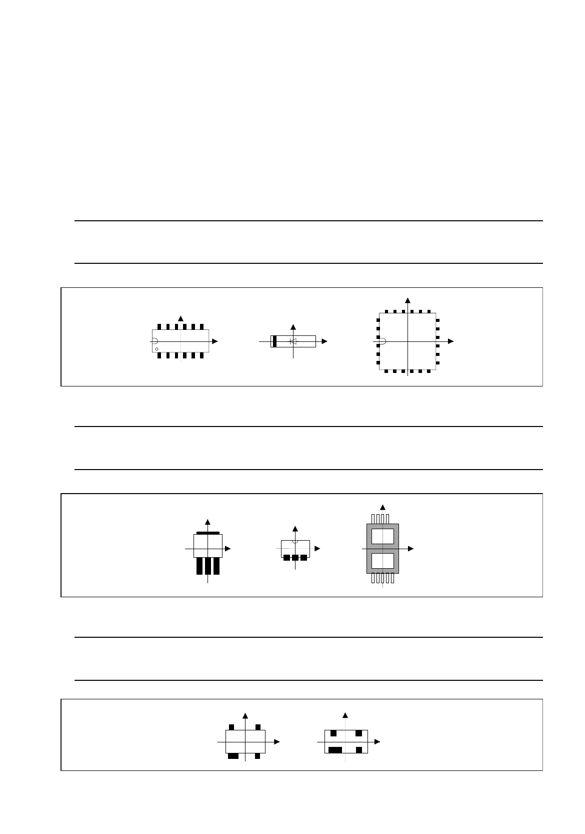
Rule: Pin 1 is to be located in the lower left corner or in the center of the component’s left side.
In the case of diodes, the anode (+) must point in positive X-direction.
Fig. 6.1.15 Position of Pin 1 and Orientation of Diodes (Examples)
Rule: The side with the higher number of pins is to be located at the bottom (negative
Y-direction).
Fig. 6.1.16 Orientation of the Side Featuring a Higher Pin Count in Negative Y-Direction (Examples)
Rule: If the component has a special feature, e.g. a wider pin, such special
feature is to be located at the bottom (negative Y-direction).
Fig. 6.1.17 Orientation of the Side Featuring Wider Pins in Negative Y-Direction (Examples)
Y
Y
X
Y
X
X
X
Y
Y
X
X
Y
Y
X
Y
X