00191413-01.pdf - 第213页
User Manual Line Computer UNIX 6 Product / Package Form Software Version 501.xx 01/99 Issue 6.1 Package Form Editor 6 - 35 Legend pertaining to Fig. 6.1. 14 ➀ The descr iption is correct - no vis ion syste m errors . ➁ V…
6 Product / Package Form User Manual Line Computer UNIX
6.1 Package Form Editor Software Version 501.xx 01/99 Issue
6 - 34
Fig. 6.1.13 X-axis of the component is aligned with the long edge of the nozzle
If the aforementioned rule is not observed, it may happen that the incorrect 0°-description will result in the errors
depicted below (see Fig. 6.1.14).
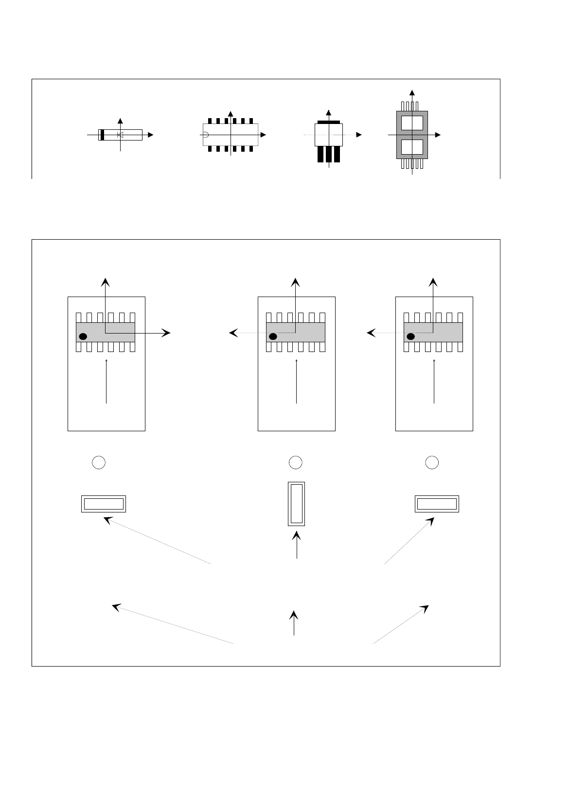
Fig. 6.1.14 0°-Description Errors
Y
X
Y
X
Y
X
Y
X
Y
X
Y
X
Y
X
0° 90° 0°
1 2 3
Correct
position of nozzle for picking up the component
transport
direction
transport
direction
transport
direction
Vacuum error
Vision system erro
r
Pick-up angle in the feeder (set-up)
0°-Description wrong0°-Description correct
User Manual Line Computer UNIX 6 Product / Package Form
Software Version 501.xx 01/99 Issue 6.1 Package Form Editor
6 - 35
Legend pertaining to
Fig. 6.1.14
➀
The description is correct - no vision system errors.
➁
Vacuum problems occur - no vision system errors.
Although the nozzle’s pick-up angle is correct, its contact position on the component is incorrect.
➂
Vision system error - no vacuum problems.
Although the nozzle makes correct contact with the component - due to the incorrect pick-up angle of 0° -
the vision system, however, expects the component in its 0°-position (which, in accordance with the 0°-
description - is vertical).
This results in the measuring windows being rotated by 90° - no evaluation is thus possible.
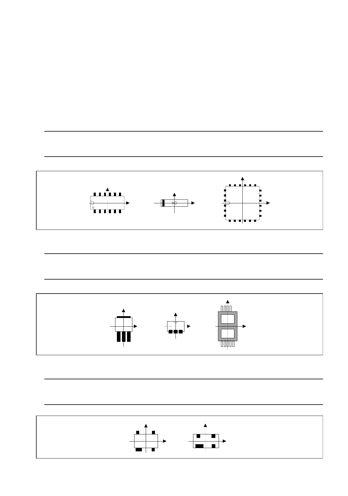
Rule: Pin 1 is to be located in the lower left corner or in the center of the component’s left side.
In the case of diodes, the anode (+) must point in positive X-direction.
Fig. 6.1.15 Position of Pin 1 and Orientation of Diodes (Examples)
Rule: The side with the higher number of pins is to be located at the bottom (negative
Y-direction).
Fig. 6.1.16 Orientation of the Side Featuring a Higher Pin Count in Negative Y-Direction (Examples)
Rule: If the component has a special feature, e.g. a wider pin, such special
feature is to be located at the bottom (negative Y-direction).
Fig. 6.1.17 Orientation of the Side Featuring Wider Pins in Negative Y-Direction (Examples)
Y
Y
X
Y
X
X
X
Y
Y
X
X
Y
Y
X
Y
X

6 Product / Package Form User Manual Line Computer UNIX
6.1 Package Form Editor Software Version 501.xx 01/99 Issue
6 - 36
6.1.3.2 Description of a Package Form of the Type "FDC"
For optical component centering by means of a Vision System, the package form of a component must be fully
described. In addition to entering the nominal dimensions and body dimension, (see section 6.1.2.5) the
following steps are required:
-
description of the pin groups
-
description of the pin models
For the performance of these steps, first the window for the description of the pin groups (see Fig. 6.1.20) is
opened. Only after a pin group has been defined can the window for the description of a pin model be opened
(see Fig. 6.1.21).
Explanation of Terms Used in GF-Data for the Description of Models and Groups of the "FDC"
Package Form Type:
-
Row all pins on one side of the component
-
Model pin shape
A model is defined by:
contact width
contact length
pin width and pin width tolerance
pin length and pin length tolerance
secondary offset of tips
-
Group a group is a number of pins of the same model (pin shape)
A group is defined by:
number of pins
identical spacing
position of the group center (secondary and primary offset)
relative to the component center
(Each group is symmetric to the group center).
Criteria for components with regular pin configuration:
-
rectangular shape
-
only one pin model (pin shape)
-
identical number of pins in horizontal direction
-
identical number of pins in vertical direction
-
identical horizontal pin spacing
-
identical vertical pin spacing
-
identical pin contact length in horizontal direction
-
identical pin contact length in vertical direction