00191413-01.pdf - 第216页
6 Product / Package Form User Manu al Line Computer UNIX 6.1 Package Form Editor Software Version 501.xx 01/99 Issue 6 - 38 Criteri a for components with irregular pin conf iguration: - rectan gular shap e - opposi te pi…
User Manual Line Computer UNIX 6 Product / Package Form
Software Version 501.xx 01/99 Issue 6.1 Package Form Editor
6 - 37
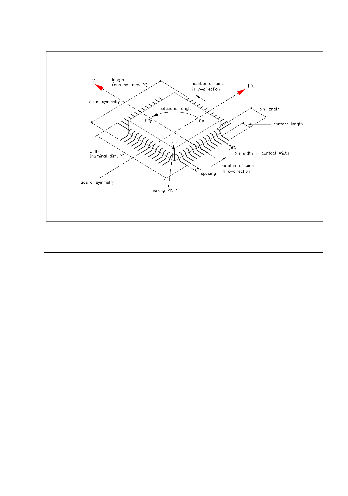
Fig. 6.1.18 Example "Regular Component"
NOTE
For component centering by means of the Vision System, the component is placed on the optical cen-
tering station so that "pin 1" is visible in the left corner at the bottom of the monitor of the Vision System.
6 Product / Package Form User Manual Line Computer UNIX
6.1 Package Form Editor Software Version 501.xx 01/99 Issue
6 - 38
Criteria for components with irregular pin configuration:
-
rectangular shape
-
opposite pin rows (horizontal or vertical) may be different, i.e. need not be symmetrical.
NOTE
The following criteria apply only to the placement of irregular components on HS-180 stations.
-
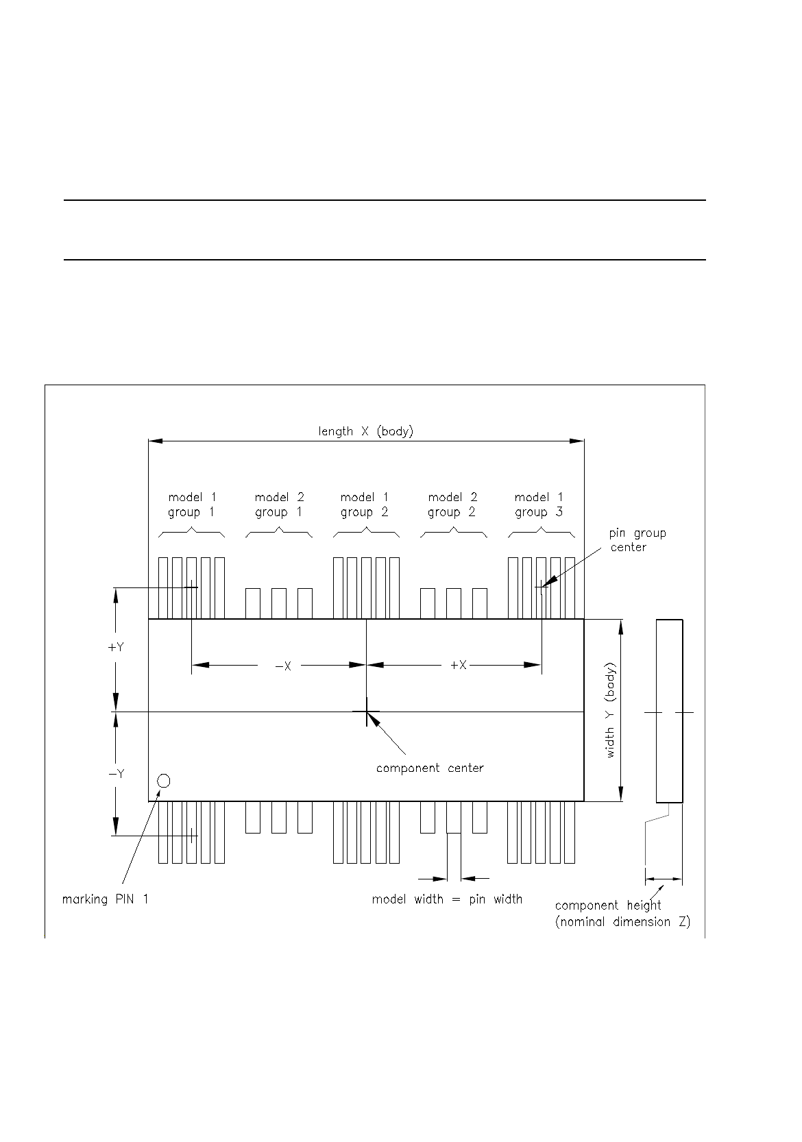
up to 3 different models (pin forms) in one row are possible.
-
in rows with 3 models a maximum of 15 pin groups can be described provided the width of any model
does not exceed the limit of 6mm.
Fig. 6.1.19 Example "Irregular Component"
User Manual Line Computer UNIX 6 Product / Package Form
Software Version 501.xx 01/99 Issue 6.1 Package Form Editor
6 - 39
Creating a pin group
Procedure:
●
Click on Create
in the command area of the "Model description" field (see Fig. 6.1.1).
The window for editing the data for the new pin group is opened (see Fig. 6.1.20).
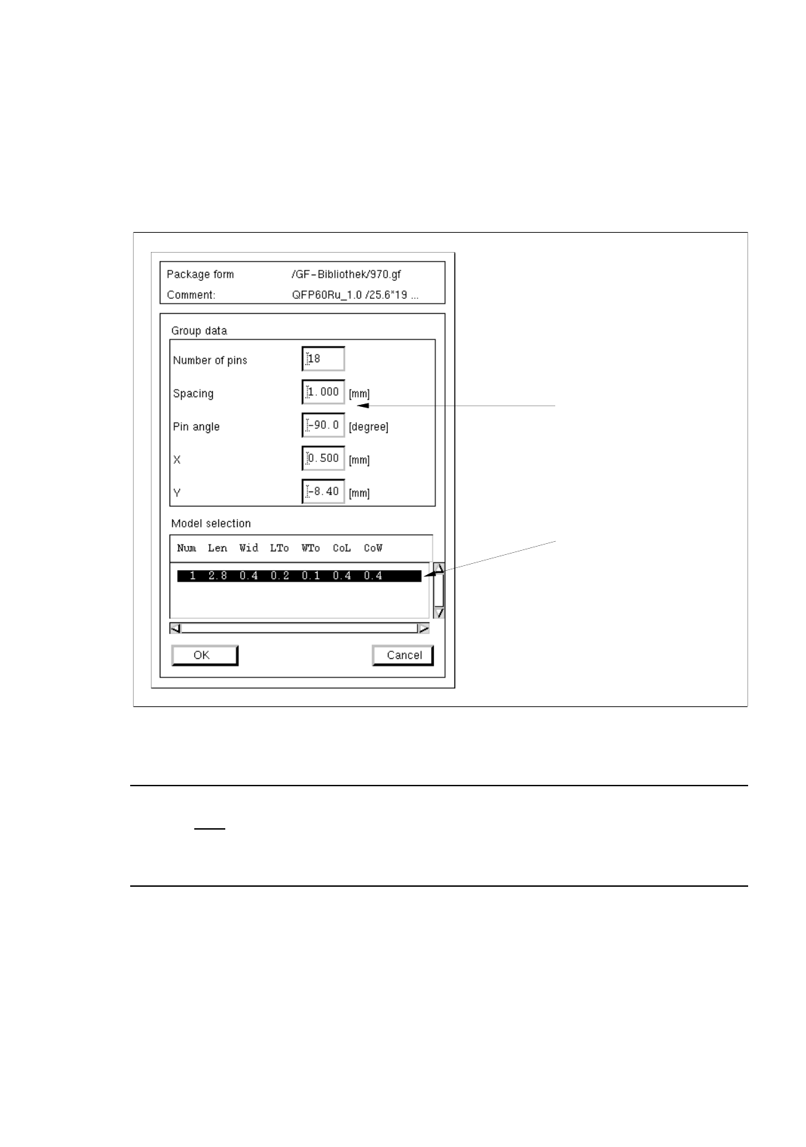
Fig. 6.1.20 Window "Group Description"
NOTE
Upon the initial
opening of the "Group description" window no entries are contained in the "Models"
selection field yet. Only after one or several pin models have been defined (see page 6 - 41) will the
data of the defined pin models be displayed in the selection field when the window is opened.
In the following, the meaning of the individual editing fields for the pin groups is explained (see also
Fig. 6.1.18 and Fig. 6.1.19).
The entries for the
offset values
"X" and "Y" and the "Pin angle" must contain the
correct signs
!
selection field
editin
g
fields
"Models"