00191413-01.pdf - 第223页
User Manual Line Computer UNIX 6 Product / Package Form Software Version 501.xx 01/99 Issue 6.1 Package Form Editor 6 - 45 6.1. 3.3 Description of a Package Form of the "BGA" Type For optic al cente ring by mea…

6 Product / Package Form User Manual Line Computer UNIX
6.1 Package Form Editor Software Version 501.xx 01/99 Issue
6 - 44
Changing a pin model
●
Select the desired pin from the view area by double-clicking.
The window for editing the data for the pin model is opened (see Fig. 6.1.21).
●
Click on editing field containing the value to be changed (cursor to be positioned in front of the
value).
●
Delete value using the DELETE key and enter new value.
(When the RETURN key is pressed in the blank field, the corresponding default value is automa-
tically calculated and entered into the field. Excepted from this are values for the pin length and
pin width because these values cannot be derived from the values already entered).
NOTE
If the current pin model is contained in several groups, the changes performed on the model data are
also transferred to those groups.
●
If the changes are to apply only to the model in the current group, the
Group only
button must be
clicked on in lieu of finishing by choosing "OK".
●
After all the required changes have been completed, click on
OK
.
If the values entered are valid, the window will be closed.

User Manual Line Computer UNIX 6 Product / Package Form
Software Version 501.xx 01/99 Issue 6.1 Package Form Editor
6 - 45
6.1.3.3 Description of a Package Form of the "BGA" Type
For optical centering by means of the Vision System, the package form of a BGA must be completely described.
For this purpose, following the entries of the nominal dimensions (see section 6.1.2.5) the following steps must
be performed:
-
description of the grid groups
-
description of the BGA models
First the window for the description of the grid group (see Fig. 6.1.25) is opened. Only after a grid group has
been defined can the window for the description of a ball model be opened (siehe Fig. 6.1.26).
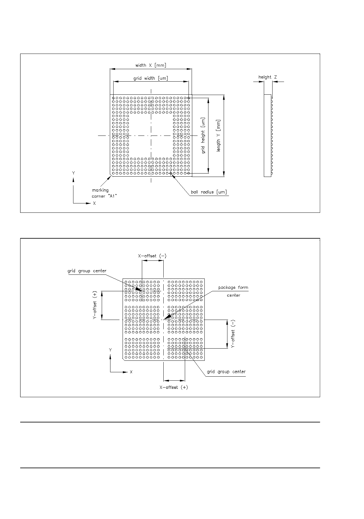
Explanation of Terms Used in GF-Data for the Description of "Ball" Models and Grid Groups
of the "BGA" Package Form Type:
-
BGA
Geometry of the "ball"
A model is defined by:
ball radius
[µ
m]
radius tolerance
[µ
m]
-
Grid group
Group of "balls" of the same model, arranged in a grid array
(grid element spacing e.g. 1.27 mm)
A grid group is defined by:
number of (vertical) columns
number of (horizontal) rows
grid width
[µ
m]
grid height [
µ
m]
position of grid group center
(x and y-offsets) relative to the
component center
[µ
m]
(each grid group is symmetric
to the group center).
6 Product / Package Form User Manual Line Computer UNIX
6.1 Package Form Editor Software Version 501.xx 01/99 Issue
6 - 46
Fig. 6.1.23 Example "Ball Grid Array comprising a single grid group"
Fig. 6.1.24 Example "Ball Grid Array comprising 6 grid groups"
NOTE
For component centering by means of the Vision System, the component is placed onto the optical centering
station so that the marking of corner "A1" (see Fig. 6.1.23) is visible in the lower left corner of the Vision
System monitor. Corner "A1" can be identified by a bevel, notch, mark or the like.