00191413-01.pdf - 第243页
User Manual Line Computer UNIX 8 Product / PCB Software Version 501.xx 01/99 Issue 8.1 PCB Editor 8 - 5 Fig. 8.1.3 E xample "Coordinates for Placements Positions, Fiducials, Ink Spots" placeme nt positi on fidu…
8 Product / PCB User Manual Line Computer UNIX
8.1 PCB Editor Software Version 501.xx 01/99 Issue
8 - 4
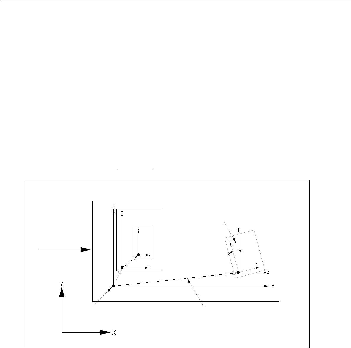
8.1.1.4 PCB Coordinate System
- Each PCB is structured hierarchically. Each structural element (PCB type) is assigned its own
coordinate system. It runs parallel to the axes of the outer edges of the structural element.
- The plane of these coordinate systems is displaced and turned. The plane of the coordinate systems of the
individual structure elements (PCB types) is displaced and rotated.
In each case they are linked to each other by a vector (see Fig. 8.1.2).
The rotational position of the coordinate systems with respect to one another is specified by an angle.
- The outer coordinate system of the entire PCB lies parallel to the axes of the machine’s coordinate system.
- The angle between the machine's coordinate system and the PCB coordinate system can be 0°, 90°, 180°
or 270°.
- The angle between coordinate systems of further partial PCB structures can be chosen as desired. It is
specified in 1/100°.
- The rotational angle is specified anticlockwise (see Fig. 8.1.2). This applies to all angular dimensions!
Fig. 8.1.2 Example "PCB Coordinate System" (PCB position in machine = 0° )"
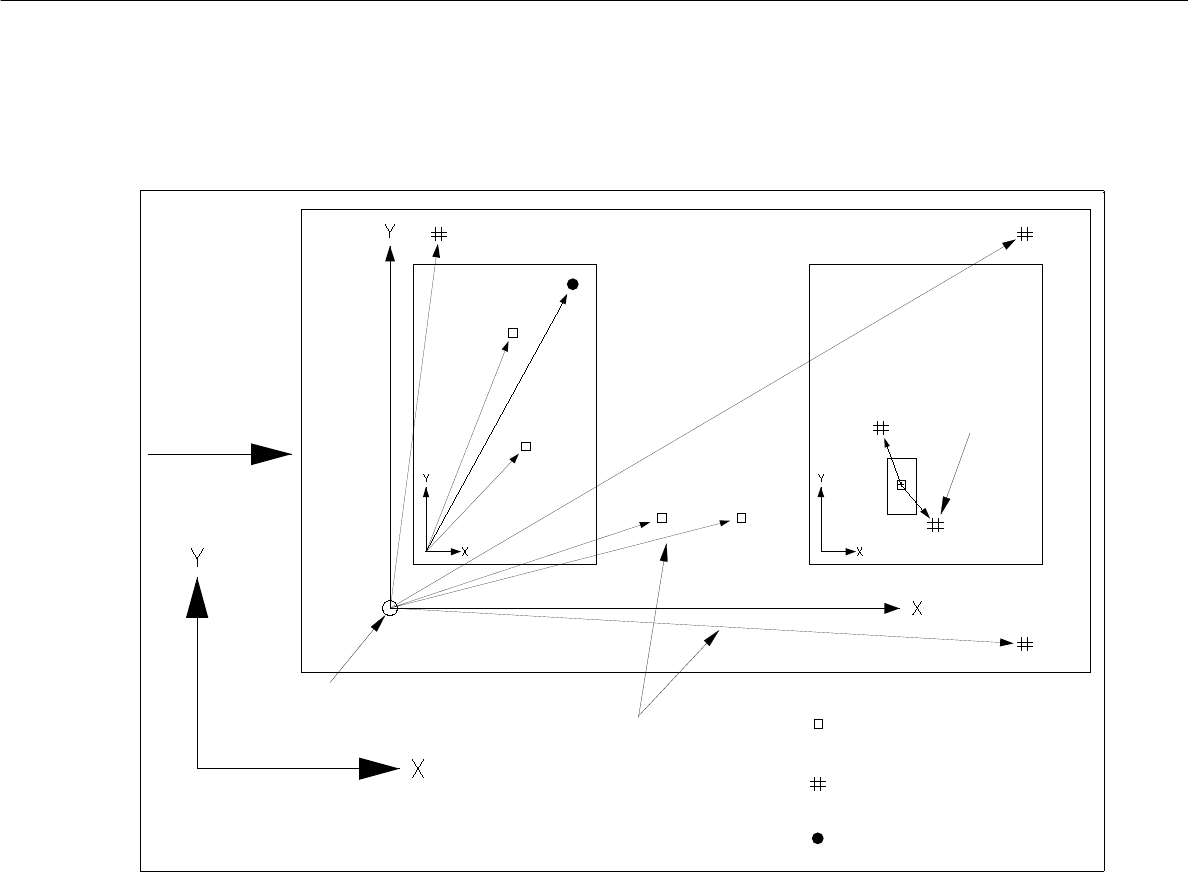
- The vectors for placement positions, fiducials and ink spots originate in the zero point of the individual PCB
type.
- The vectors for fiducials of the placement positions originate at the placement position.
PCB zero point
machine’s coordinate system
direction of
vectors
rotational angle
PCB transport
User Manual Line Computer UNIX 8 Product / PCB
Software Version 501.xx 01/99 Issue 8.1 PCB Editor
8 - 5
Fig. 8.1.3 Example "Coordinates for Placements Positions, Fiducials, Ink Spots"
placement position
fiducial (PM)
ink dot
vectors
PCB transport-
machine’s coordinate system
fiducial for
placem. pos.
PCB zero point
direction
recognition
8 Product / PCB User Manual Line Computer UNIX
8.1 PCB Editor Software Version 501.xx 01/99 Issue
8 - 6
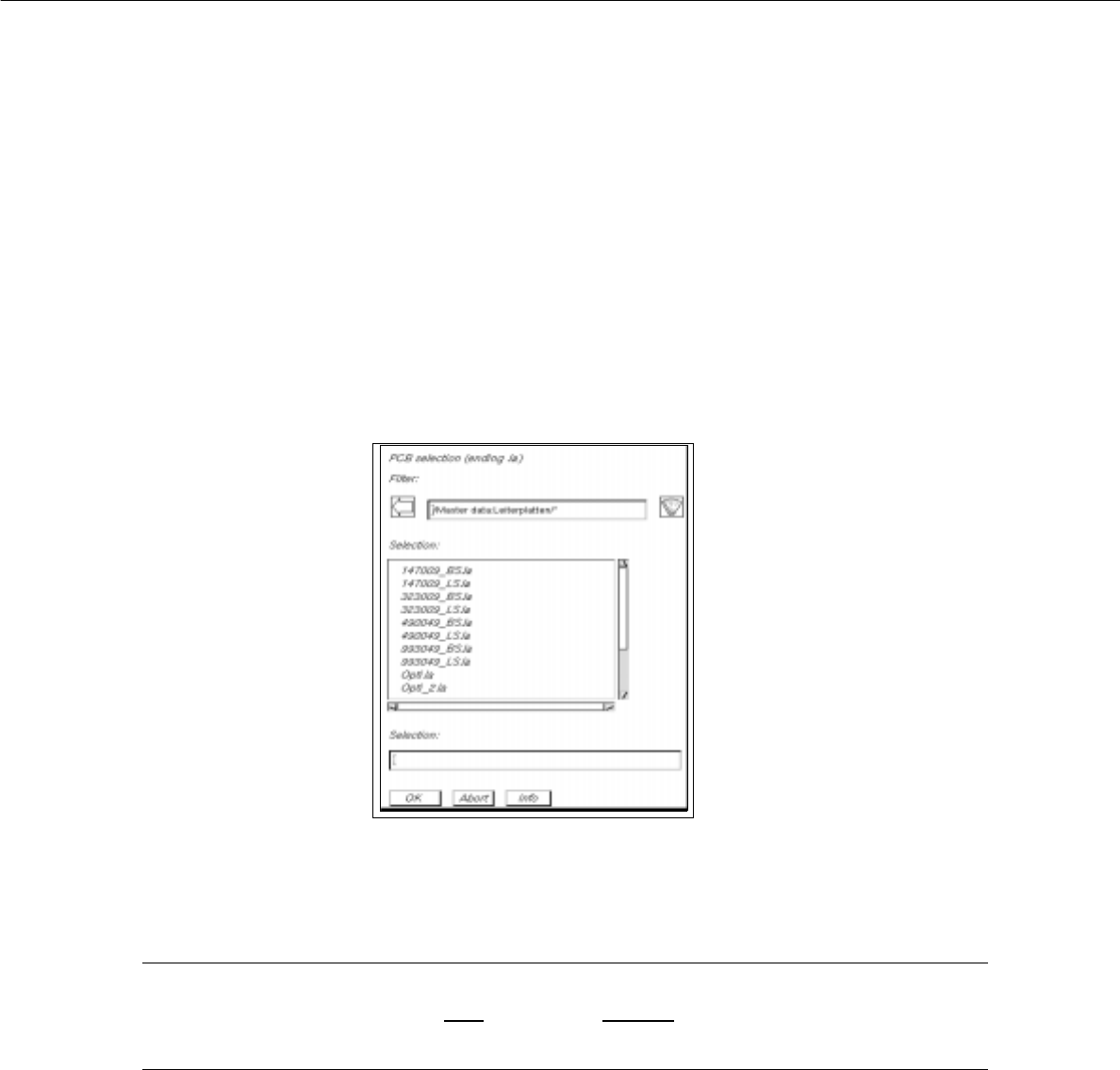
8.1.2 Starting the PCB Editor
- In the "programming mode" the PCB Editor is activated by clicking on the PCB icon on the desktop or
via the Data Manager (see chapt. 4).
- If the LC program was installed for the "control mode", the PCB Editor can be started via the
"PRODUCT" menu on the desktop, or via the Data Manager.
● Click on the PCB icon on the desktop (or the "PCB Editor" option on the "PRODUCT" menu).
The FSB containing the files of all already-defined PCBs is opened.
● Select name "xxx.la" of the PCB desired by double-clicking, or enter the new number using the
keyboard and confirm with OK.
The main window of the PCB Editor, the so-called Structure Editor (see Fig. 8.1.4), is opened.
NOTE
The name of the PCB may comprise max.
20 characters including the suffix ".la". Some characters
must not be used for the name, see chapt. 2, section 2.3 in this connection.