00191413-01.pdf - 第257页
User Manual Line Computer UNIX 8 Product / PCB Software Version 501.xx 01/99 Issue 8.1 PCB Editor 8 - 19 ● Acti vate or d eactiva te the desi red dis play option s (grap hical elem ents) by clicki ng on the respec tive b…
8 Product / PCB User Manual Line Computer UNIX
8.1 PCB Editor Software Version 501.xx 01/99 Issue
8 - 18
Settings:
- Setting the zoom factor
● Click on the editing field "Zoom" and enter the desired value (10 to 999).
● To accept the entry, press the RETURN key.
The PCB is displayed in the desired size.
- Entering the placement level
The placement level number can be entered in the "Level" editing field. This serves to identify the
placement positions allocated to the respective placement level (see section 8.1.6, page 8 - 40) in the
graphical display of the PCB.
NOTE
The editing field will contain a broken line "-----" if no placement levels are defined or if no placement
level was entered.
I no placement levels have been defined, no entries are possible.
● Click on the "Level" editing field and enter the number of the desired placement level, or select
the placement level using the arrow keys and then press the RETURN key.
If the "PP markings" display option (see page 8 - 19) is activated, at a minimum, the placement
positions of the currently selected level are displayed - highlighted in blue.
Selecting display options
To obtain a clearly arranged display of the PCB, the respectively required graphical elements can be sel-
ected individually (e.g. only the display of the PCB fiducials).
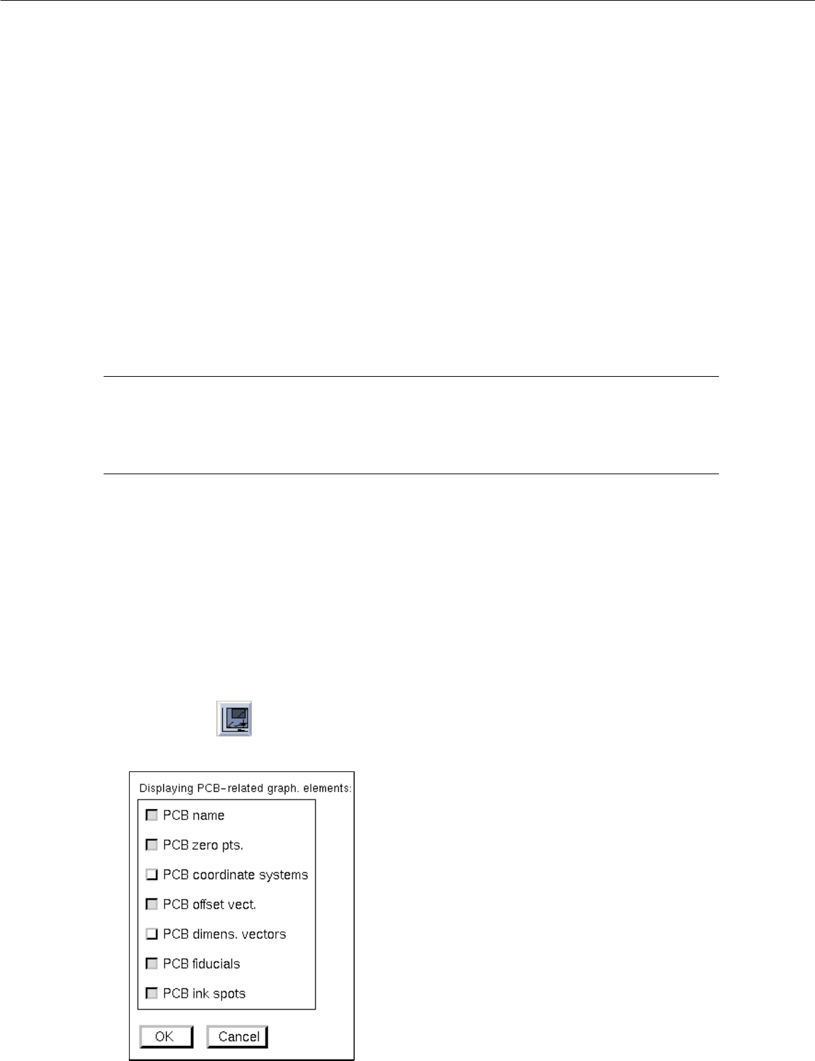
- Displaying PCB-related graph. elements
● Click on icon .
The following window opens:
User Manual Line Computer UNIX 8 Product / PCB
Software Version 501.xx 01/99 Issue 8.1 PCB Editor
8 - 19
● Activate or deactivate the desired display options (graphical elements) by clicking on the
respective buttons.
● Click on OK.
The window closes, and the PCB with the selected graphical elements is displayed in the display
area (see Fig. 8.1.6).
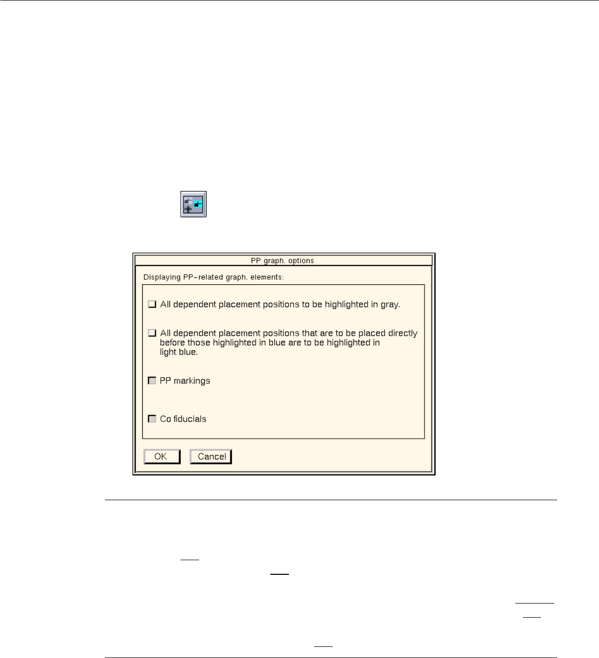
- Displaying PP-related graph. elements
● Click on the icon.
The following window opens:
NOTE
- If the topmost button in the window and the "PP markings" button are activated and if no place-
ment level is entered, all placement positions that are associated with placement levels are displayed
highlighted in gray
. If a placement level is entered, the placement positioned allocated to this
level are displayed - highlighted in blue
.
- If the second button and the "PP markings" button are activated, all placement positions associated
with the placement level preceding the currently selected placement level, are highlighted in light blue
.
The placement positions allocated to the currently selected placement level are highlighted in blue
.
- If the "PP markings" button is activated and if a placement level is entered, the placement positions
associated with that level are highlighted in blue.
● Activate or deactivate the desired display options by clicking on the appropriate buttons.
● Click on OK.
The window closes.
● Enter a placement level, if required (see page 8 - 40).
The selected graphical elements are displayed in the view area in the appropriate colors.
8 Product / PCB User Manual Line Computer UNIX
8.1 PCB Editor Software Version 501.xx 01/99 Issue
8 - 20
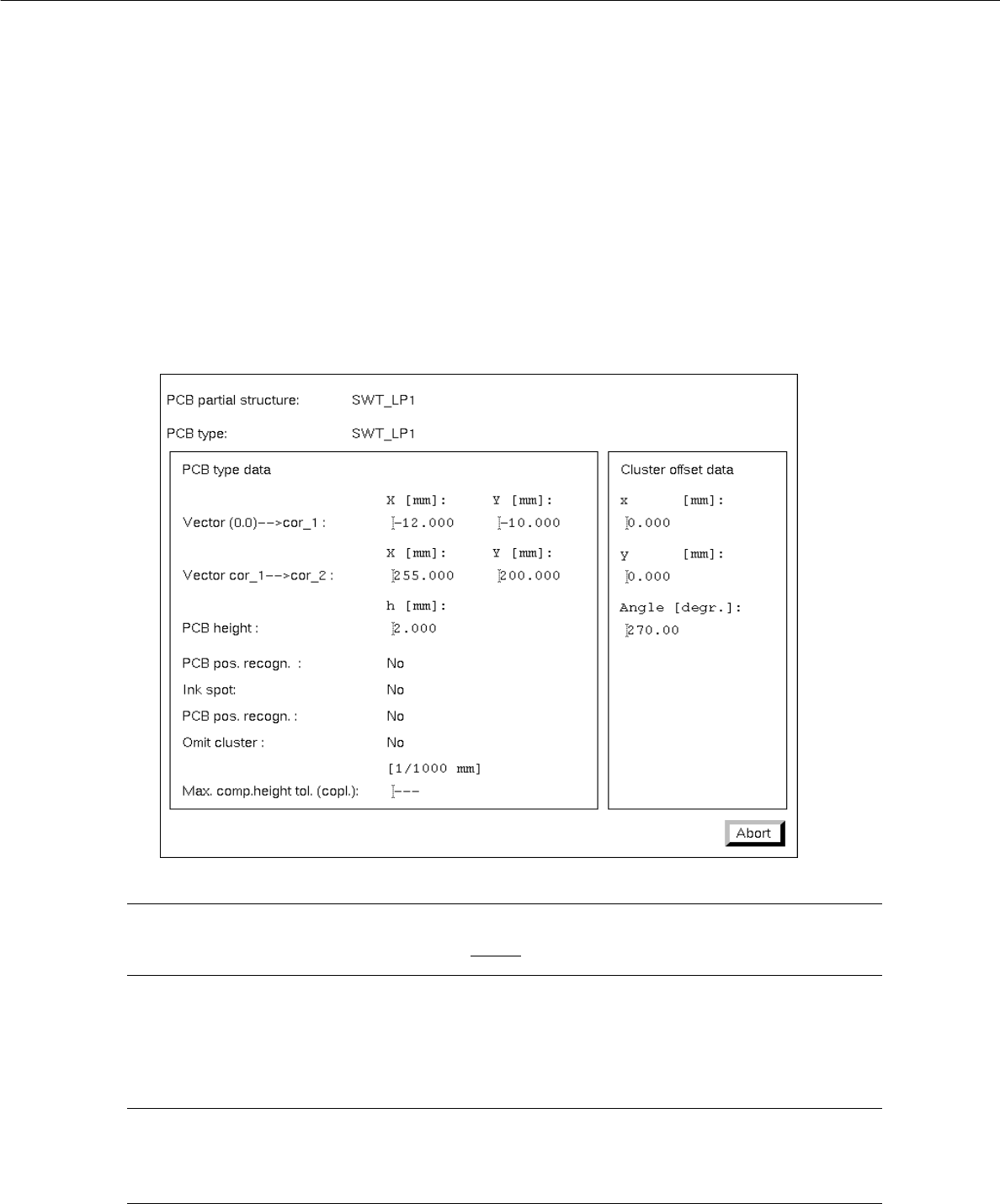
8.1.3.5 Display of the Cluster Data in the Structure Editor (Graphic Mode)
In the Graphic Mode of the Structure Editor the cluster data of the PCB and those of every substructure can
be displayed in separate windows.
● Select the outline of the PCB structure by double-clicking on it.
The outline is highlighted by a selection frame in bold type.
The "PCB info" window containing the cluster data of the selected structure is opened.
NOTE
The data contained in the "PCB info" window cannot be changed.
● Click on the Abort button.
The "PCB info" window is closed.
NOTE
In addition, the "PCB info" window can be opened for a substructure from the "PP information"
window (see page 8 - 21).