00191413-01.pdf - 第273页
User Manual Line Computer UNIX 8 Product / PCB Software Version 501.xx 01/99 Issue 8.1 PCB Editor 8 - 35 NOTE If a fiducial within a fi ducial se t has alrea dy been de fined as a n ink spot for the recogn ition of a fau…

8 Product / PCB User Manual Line Computer UNIX
8.1 PCB Editor Software Version 501.xx 01/99 Issue
8 - 34
8.1.5.2 Command Area of Fiducial Editor
Depending on which settings have been selected in the command area (see Fig. 8.1.10) , the corresponding
actions are performed with respect to the fiducial sets and fiducials.
COMMANDS
- Inserting
When this command is activated, existing fiducial sets and fiducials can be edited in the appropriate
editing fields.
● Activate Insert in the command area.
● With a mouse-click select the fiducial set and fiducial in the respective display area.
The names of the fiducial set and the fiducial and the data of the fiducial are displayed in the
editing fields.
- Deleting Fiducial Set
● Activate Delete fiducial set.
● Select fiducial set in the display area with a mouse-click.
Fiducial set will be deleted (without confirmation!).
CAUTION
"Delete fiducial set" is to be deactivated by selecting another command, as otherwise any other fidu-
cial set that may subsequently be clicked on in the display area will also be deleted.
- Blocking Fiducial Set
With this command it is possible to block a fiducial set for a given PCB type loaded and thus to ignore
it when assembling the PCB.
● Activate Block fiducial set.
● Click on fiducial set.
The name displayed is now preceded by "S". Clicking on the fiducial set once more causes the
"blocking" to be cancelled.
- Ink Spot Fiducial Set
With this command it is possible to define a fiducial set for ink dot recognition of the PCB type loaded.
● Activate Ink spot fiducial set.
● Click on fiducial set.
The name displayed is now preceded by "I". Clicking on the fiducial set once more causes the
action to be reversed again.
User Manual Line Computer UNIX 8 Product / PCB
Software Version 501.xx 01/99 Issue 8.1 PCB Editor
8 - 35
NOTE
If a fiducial within a fiducial set has already been defined as an ink spot for the recognition of a faulty PCB
type (see command "Ink spot fiducials"), an "I" is automatically displayed next to the name of the fiducial
set concerned. If the command "Ink spot fiducial set" is active and the fiducial set marked by an "I" is clik-
ked on, the ink spot definition for the respective fiducial within the fiducial set is cancelled.
- PCB Position Recognition
With this command it is possible to define a fiducial set for PCB position recognition of the PCB type
loaded.
● Activate PCB position recognition.
● Click on fiducial set in the display area.
The name of the fiducial set selected is now preceded by "L".
Clicking on the fiducial set once more causes the action to be reversed again.
NOTE
To be able to perform the following actions involving fiducials, it is necessary to first select the
appropriate fiducial set.
- Deleting Fiducials
● Activate Delete fiducials.
● Click on fiducial.
Thereafter, the fiducial will be deleted (without confirmation!).
CAUTION
"Delete fiducial" is to be deactivated by selecting another command, as otherwise any other fiducial
that may subsequently be clicked on in the display area will also be deleted.
- Blocking selected Fiducials
With this command it is possible to block a fiducial of the selected fiducial set and thus to ignore it
when assembling the PCB.
● Activate Block fiducials.
● Click on fiducial.
The name displayed is now preceded by "S".
Clicking on the fiducial once more causes the action to be reversed again.
- Defining Ink spot as Fiducial
This command is used to define a fiducial from a fiducial set as an ink spot to identify the PCB type
loaded as one to be rejected.
● Activate Ink spot fiducials.
● Click on fiducial.
The name displayed is now preceded by "I".
Clicking on the fiducial once more causes the action to be reversed again.
8 Product / PCB User Manual Line Computer UNIX
8.1 PCB Editor Software Version 501.xx 01/99 Issue
8 - 36
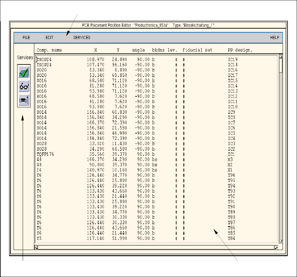
8.1.6 Window of Placement Position Editor
A Placement Position Editor can be opened for every PCB type generated (see description on page 8 - 10).
In the following, the areas of the Placement Position Editor window and their functions are explained.
Fig. 8.1.11 Window "Placement Position Editor"
The window of the Placement Position Editor is subdivided as follows:
- Menu bar
- Display area
- Editing area
- Command area
menu bar
editing area
command area