00191413-01.pdf - 第277页
User Manual Line Computer UNIX 8 Product / PCB Software Version 501.xx 01/99 Issue 8.1 PCB Editor 8 - 39 - Mirror-inverting PP positions a bout the x-axis The sign s of all value s entered i n the ed iting area u nder &q…
8 Product / PCB User Manual Line Computer UNIX
8.1 PCB Editor Software Version 501.xx 01/99 Issue
8 - 38
8.1.6.1 EDIT MENU
- Resetting Placement Position data
The entries already existing for the PCB type concerned can be deleted from the editing area.
● Click on EDIT --> Reset placement position.
The editing area is empty, new entries can be made.
NOTE
If the PCB Editor is exited from without activating "Save" (in the Structure Editor), the old data will be
displayed again when the Placement Position Editor is called up.
- Loading placement position of an existing PCB type
This function enables a placement program of another PCB type to be loaded into the Placement
Position Editor of the current PCB type.
● Activate icon in the command area of the current Structure Editor.
● Select partial PCB structure (target).
● Click on SERVICES --> Placement Position Editor.
The window of the Placement Position Editor is opened.
● Click on FILE --> Open....
The FSB for the selection of the (source) PCB is opened (see page 8 - 6).
● Select PCB by double-clicking.
The main window of the new Structure Editor is opened.
● Click on the partial PCB structure containing the PP data to be copied (source).
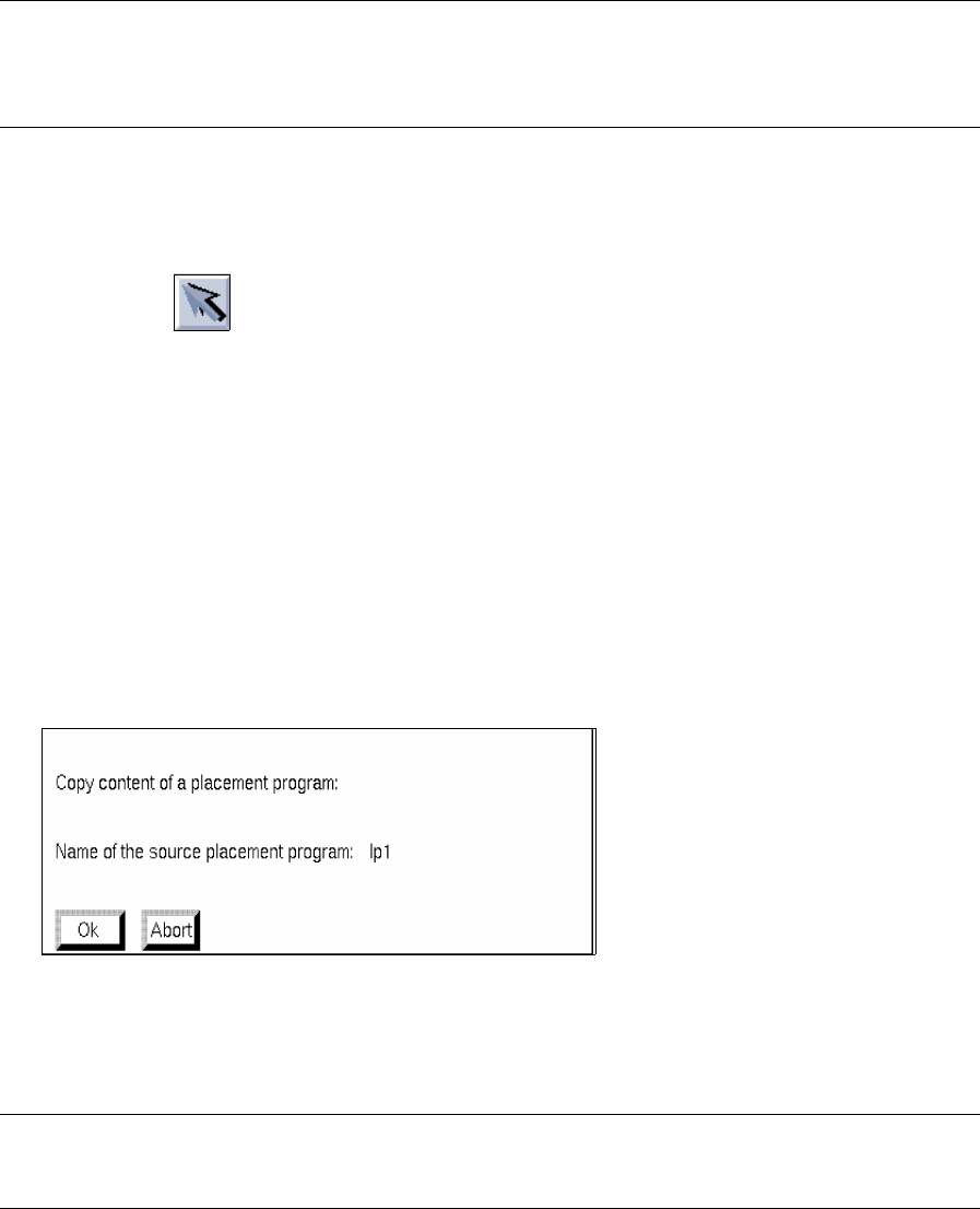
● Activate EDIT --> Load placement position from in the current Placement Position Editor (target).
The following dialog box appears:
● Confirm dialog box with OK .
The loaded placement program is displayed in the window of the Placement Position Editor.
NOTE
If data had already been entered in the editing area, these will be replaced with the copied data.
User Manual Line Computer UNIX 8 Product / PCB
Software Version 501.xx 01/99 Issue 8.1 PCB Editor
8 - 39
- Mirror-inverting PP positions about the x-axis
The signs of all values entered in the editing area under "Y" (placement positions in y-direction) are
reversed.
● Click on EDIT --> Mirror-inverting placement positions about the X-axis.
All positive values entered (prior to the above clicking action) under "Y" are now displayed with a
negative sign preceding the entries, all previous negative values are now displayed as positive values.
- Mirror-inverting PP positions about the Y-axis
The signs of all values entered in the editing area under "X" (placement positions in x-direction) are
reversed.
● Click on EDIT --> Mirror-inverting placement positions about the Y-axis.
8.1.6.2 SERVICES Menu
- Opening the Cluster Editor
● Click on SERVICES --> Cluster Editor.
The window of the Cluster Editor is opened (see Fig. 8.1.8).
8.1.6.3 Editing Area of the Placement Position Editor
INPUT POSSIBILITIES:
- Comp. name name of the component (max. 11 characters)
- X, Y placement position in x and y-directions (referred to the PCB zero point);
it is possible to enter 3 decimal places before and 3 decimal places behind
the decimal point.
- angle angle at which component is placed during placement operation (-360° to
+360°) referred to the PCB coordinate system; it is possible to enter 3
decimal places before and 2 decimal places behind the decimal point.
- bkdns scheduling the processing sequence (process-specific data);
b = placing, k = gluing, d = dispensing (solder paste metering),
n = reworking, (must be entered in combination with "b", "k" or "d".
However, it must not be combined with "s")
s = blocking (must be entered in combination with "b", "k" or "d".
However, it must not be combined with "n")

8 Product / PCB User Manual Line Computer UNIX
8.1 PCB Editor Software Version 501.xx 01/99 Issue
8 - 40
- lev. Number of the placement level (number between 1 ... 9999, # = level 0)
NOTE
If, for example, components of extremely varying heights are to be placed very closely next to one
another, it is necessary to define a placement sequence with the aid of placement levels in order to
avoid problems during the placement process. However, at present such a placement sequence is
only defined with respect to components that need to be placed with the IC head.
The level numbers entered determine the sequence in which the placement positions will be pro-
cessed. The placements will be processed in accordance with the level numbers, in an ascending
order.
Placement positions that were assigned the same level, will be processed within that level in any
order whatever.
Placement positions that were not assigned any specific level may be processed at any level.
Placement positions to which placement level 0 (#) has been assigned are processed before
all other
placement positions with different placement levels.
- Max. 9999 placement levels can be assigned.
- Every placement position can be assigned one level.
- Any one level can be assigned several placement positions.
- The levels do not need to be numbered consecutively.
- fiducial set Name of fiducial set (max. 11 characters; # = no fiducial set)
- Comment freely selectable, e.g. component type
PROCEDURE to be followed for editing:
- Editing
● Position mouse cursor in the editing area and make entries from the keyboard.
A space must be left between entries of individual columns.
● Finish the completed input line with RETURN.
● After completing the entries, click on the icon in the command area (see Fig. 8.1.11).
The individual entries are now checked and placed in the corresponding columns.
If an incorrect entry has been made, the entire editing area is surrounded by a red frame and an
error message is displayed on the screen.
● If applicable, confirm the error message by clicking on OK.
The dialog box is closed and the cursor is automatically positioned, within the editing area, at the
location of the incorrect entry.
- Copying entries in the Placement Position Editor within one and the same window or to another open
Placement Position Editor window.
● Hold down the left mouse button and move the mouse cursor over the entries to be copied (exa-
ctly to the end of the last character) and then release the mouse button.
The lines concerned now darken.
● Hold down the center mouse button and position the cursor to the position in the editing area of
the respective window of the Placement Position Editor where the lines are to be inserted and
then release the mouse button.
The copied entries are now displayed.