00191413-01.pdf - 第309页
User Manual Line Computer UNIX 10 Production Tools / Restrictions Software Version 501.xx 01/99 Issue 10.1 Restriction Editor 10 - 3 10.1.3 Main Window of Restriction Editor The areas of the mai n window an d their fu nc…

10 Production Tools / Restrictions User Manual Line Computer UNIX
10.1 Restriction Editor Software Version 501.xx 01/99 Issue
10 - 2
10.1.1 Allocation Possibilities
A production job is carried out on a given line. For set-up optimization purposes it is possible to define allocations
relating to this job. The possibilities that can be chosen from are described below:
- It is possible to specify where and how often a component is to be set up on the line, and
where it must not be set up under any circumstances.
Binding ---> The component must
be set up on the particular "individual". In addition,
the binding can define how often the component is to be set up and which
feeder or waffle-pack tray is to be used. If no feeder or waffle-pack tray is
stated, the feeding unit (feeder/waffle-pack tray) defined in the ".ri"-file is used.
The component can also be "bound" to the complete line.
Exclusion ---> The component must not
be set up on the particular "individual" specified.
- The default feeder defined in the ".ri"-file (see chapt. 9) with respect to a component/machine
combination may (in connection with a specific production job) be replaced by an alternative
feeder.
It is thus possible to appropriately respond to short-term temporary situations such as a different form
of component supply, for a limited period of time.
10.1.2 Starting the Restriction Editor
- In the "programming mode", the Restriction Editor is activated by clicking on the Restrictions icon on
the desktop, or via the Data Manager (see chapt. 4).
- If the LC program was installed for the "control mode", the Restriction Editor can be started via the
desktop menu "PRODUCTION TOOLS", or via the Data Manager.
● Click on the Restrictions icon on the desktop (or the menu option "Restriction Editor" on the menu
"PRODUCTION TOOLS"). The main window of the Restriction Editor is opened (see Fig. 10.1.1).
NOTE
Moreover, the Restriction Editor can be started via the user interface of the Data Manager by
selecting the ".rs" restriction file in the path "Job data/Losplanung/xx.lose/*". The procedure to be
followed for starting the Restriction Editor via the user interface of the Data Manager is described in
chapt. 4, section 4.3.4 of this manual.
User Manual Line Computer UNIX 10 Production Tools / Restrictions
Software Version 501.xx 01/99 Issue 10.1 Restriction Editor
10 - 3
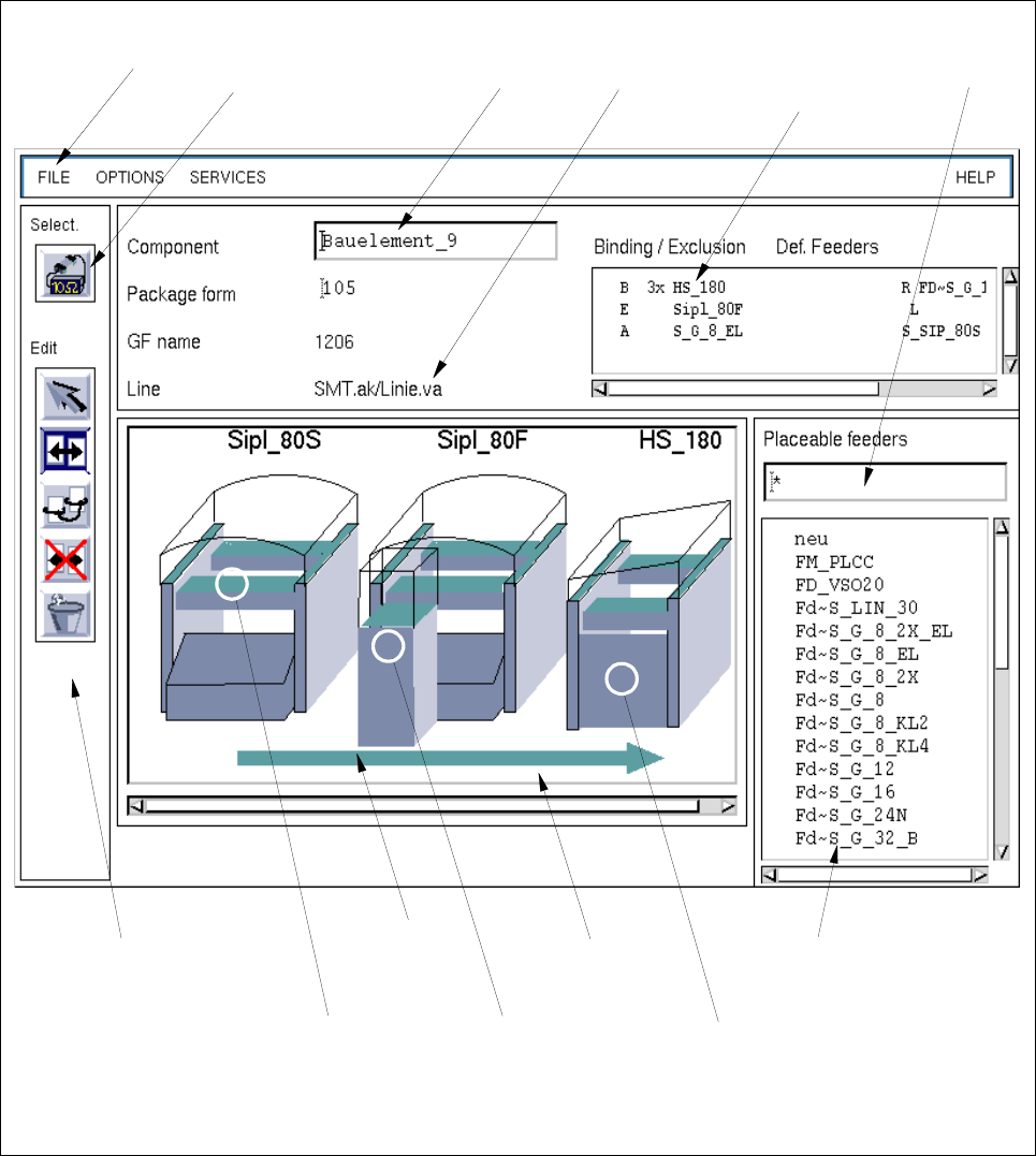
10.1.3 Main Window of Restriction Editor
The areas of the main window and their functions are explained in the following.
Fig. 10.1.1 Main Window "Restriction Editor"
selection field
"Placeable feeders"
display area
command area
menu bar editing field
"Component"
selection field
"Restrictions/
filter field
selection area
"Component"
name of the
line
Allocations"
selection:
complete
machine type
selection:
WPC trolley
(SIPLACE 80F)
selection:
complete line
selection:
feeder part on
the right
machine side
10 Production Tools / Restrictions User Manual Line Computer UNIX
10.1 Restriction Editor Software Version 501.xx 01/99 Issue
10 - 4
The main window is subdivided as follows:
- Menu bar
- Selection area
- Editing field
- Display area
- Selection fields
- Filter field
Menu Bar
The menu bar contains the menus "FILE", "OPTIONS", "SERVICES" and "HELP".
The "SERVICES" menu is described in section 10.1.3.1.
NOTE
Since the functions and operation of the menus "FILE", "OPTIONS" and "HELP" are similar to those in
other application programs of the line computer, they described in detail in chapt. 2.
Selection area "Component"
In this area, the component is symbolized by an icon by means of which the FSB for the selection of a new
component can be opened. The procedure to be followed is described in section 10.1.3.2.
Editing field "Component"
In this field, the name of the desired component is entered for which an allocation or restriction is to be defined.
Display area
In the display area, only those stations and station extensions of a line together with their feeder locations are
displayed symbolically, that are required for the production of the jobs contained in the lot file.
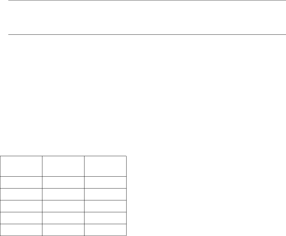
Depending on the currently active mode of the editor, the locations for which bindings and exclusions have
been defined are displayed in color (see chart below).
Selection fields
Selection field "Restrictions/Allocations"
In this field, all bindings, exclusions and allocations are displayed that were defined for the current
component.
Mode Binding
(yellow)
Exclusion
(red)
Selection
x x
Allocation
--
Binding
x-
Exclusion
-x
Deletion
--