00191413-01.pdf - 第315页
User Manual Line Computer UNIX 10 Production Tools / Restrictions Software Version 501.xx 01/99 Issue 10.1 Restriction Editor 10 - 9 Defining bindi ngs to the com plete li ne : ● Clic k on arrow below the d ispla y of th…
10 Production Tools / Restrictions User Manual Line Computer UNIX
10.1 Restriction Editor Software Version 501.xx 01/99 Issue
10 - 8
- (Allocate)
When this icon is active, the editor is in the allocation mode. The current component can be allocated
to alternative feeders or alternative waffle-pack trays. They temporarily replace for this current produc-
tion job the default feeding units that are entered for the current component (package form) in the ".ri"-
file (see chapt. 9).
● Click on icon in the command area.
● Click on the location (feeder part or entire machine) in the display area where the alternative
feeder or waffle-pack tray with the current component is to be set up. The selected element is
now highlighted in green.
● Select feeder or waffle-pack tray from the "Placeable feeders" selection field.
The name of the allocated feeder or waffle-pack tray is displayed in the selection field
"Restrictions/Allocations", preceded by the letter "A".
Behind the name the machine type is entered on which the current component is to be set up.
If a particular feeder part is selected, also the side is entered on which the feeder part is located,
with the letter "L" designating the left side and "R" the right side.
Example: Z S_G_8_EL S_SIP_80S L
Feeder Machine type Side
(SIPLACE 80S) ("left" as seen in the direction of travel)
NOTE
Double-clicking on an entry in the selection field "Placeable feeders" causes the window for
editing the feeder or waffle-pack tray data to be opened (see chapt. 9, Figs. 9.1.3 and 9.1.4).
- (Bind)
When this icon is active, the editor is in the mode which allows bindings for the current component to
be defined.
● Click on icon in the command area.
Defining bindings
to a feeder part or a machine:
● Click on the location (feeder part or entire machine) in the display area on which the current com-
ponent must be set up. All locations for which bindings were already defined, are now highlighted
in yellow. In addition, the window for the definition of bindings is opened (see Fig. 10.1.2).
User Manual Line Computer UNIX 10 Production Tools / Restrictions
Software Version 501.xx 01/99 Issue 10.1 Restriction Editor
10 - 9
Defining bindings
to the complete line:
● Click on arrow below the display of the stations (see Fig. 10.1.1).
The window for the definition of bindings is opened (see Fig. 10.1.2).
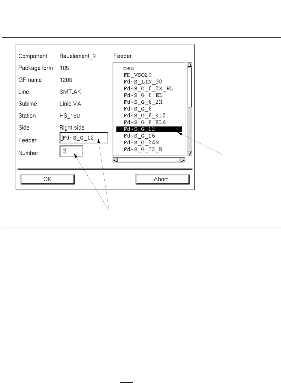
Fig. 10.1.2 Window for the Definition of Bindings
Meaning of the editing fields
- Feeder
Name of the particular feeder or waffle-pack tray by means of which the current component must be
set up at the selected location.
NOTE
Any entry in the editing field "Feeder" is not required.
If no entry is made the default or alternative feeding unit (feeder or waffle-pack tray) specified for the
component and the machine is automatically defined.
- Number
Indicates how often the current component must
be set up at the selected location. As default value a
"1" is entered.
selection field
"Feeder"
editing fields
10 Production Tools / Restrictions User Manual Line Computer UNIX
10.1 Restriction Editor Software Version 501.xx 01/99 Issue
10 - 10
Defining bindings:
Defining a particular feeding unit:
● Select the desired feeding unit (feeder or waffle-pack tray) from the "Feeder" selection field (see
Fig. 10.1.2). The name of the selected feeding unit is entered in the "Feeder" editing field.
Or else:
● Click on the "Feeder" editing field and enter the name of the desired feeding unit.
Defining the quantity:
● Click on the "Number" editing field, delete the default value using the DELETE key and enter the
desired quantity.
● Click on OK for the entered data to be accepted.
The window is closed.
All locations where the current component must be set up are now highlighted in yellow. (If the com-
plete line is selected, the binding is not highlighted in color).
In the selection field "Restrictions/Allocations" the number stating how often the current compo-
nent must be set up at the selected location, the names of the machine type and the feeding unit
are displayed. If a particular feeder part was selected, the side on which the feeder part is
located is entered in addition. The entry as a whole is identified by a "B" (for "binding").
Example: B 3x HS_180 R FD~S_G_8_EL
Number of Machine type Side Feeding unit
bindings (HS-180) (8mm-tape feeder, electric)
Example of a binding to a complete line (without the selection of a feeding unit):
B 6x SMT.ak/line.va
Number of Name of line/name of subline
bindings
- (Exclude)
When this icon is active, the editor is in the mode which allows exclusions for the current component
to be defined.
● Click on icon in the command area.
● In the display area, select the location (feeder part or entire machine) at which the current compo-
nent with the feeder allocated to it must not
be set up (see Fig. 10.1.1). The selected location and
all other locations for which exclusions have already been defined are now highlighted in red.