00191413-01.pdf - 第336页
11 Production Tools / Optimization User Manual Line Computer UNIX 11.3 Setup Optimization Software Version 501.xx 01/99 Issue 11 - 16 In addition to the mac hine type, the time functions ar e also depende nt on the diffe…

User Manual Line Computer UNIX 11 Production Tools / Optimization
Software Version 501.xx 01/99 Issue 11.3 Setup Optimization
11 - 15
11.3.3.11 Handling of Dominant Vibration Times
In some instances the placement time largely depends on the vibration times of the feeders. This is always the
case if the turret head needs to place the same component type very frequently. In this case, the turret head
accesses the same feeder compartment several times in succession. Owing to the fact that in most instances
the pick-up speed of the turret head is greater than the feeding speed of the feeder, waiting times are likely to
occur. To prevent this from happening, components with a high usage rate are set up at several locations.
Prerequisite: If the percentage of the placement positions of a particular component is larger than or
equal to 20% compared with the total placement positions to be populated by the turret
head, and if the vibration time of the feeder is longer than the the cycle time of the turret
head, the component is set up a second time provided the capacity of the feeder part
concerned is sufficiently large.
However, if a dominant component is not to be set up any number of times, e.g. because a sufficient number
of feeders is not available, the number of feeders per component type can be restricted. This has the advantage
that a component type occupies only a limited number of feeder locations. However, this may result in an
increase of the production time since the components are not always located at the most advantageous
locations. Moreover, several setup clusters („families“) may under certain circumstances be calculated even
though one single setup would have sufficed.
This setting is to be set in the standard/job parameters by means of the „Maximum number if dominant“
parameter (see section 11.4.3.1).
11.3.3.12 Nozzle Minimization
In „nozzle minimization“ the number of nozzles per head and PCB type is used for the calculation.
● For the IC-head, nozzle minimization is carried out per PCB type.
● Also for the turret head, a nozzle minimization run is performed for each PCB type.
Furthermore, the particular nozzle configuration at the head is determined which results in a minimum of
placement cycles.
NOTE
The nozzle configuration can be displayed with the producibility check results.
11.3.3.13Times Taken Into Account
For setup optimization the times listed in the following are taken into account:
● Time required for one movement of the IC-head or turret head, respectively.
To be able to calculate the placement times as accurately as possible, time functions were recorded
at selected placement machines. These times were measured separately for SIPLACE 80S/80F and
HS-180 machine types.
11 Production Tools / Optimization User Manual Line Computer UNIX
11.3 Setup Optimization Software Version 501.xx 01/99 Issue
11 - 16
In addition to the machine type, the time functions are also dependent on the different head types such as
turret head and IC-head as well as the 3 axes x, y and z.
The time functions determined at the placement machines are directly included in the calculation of the
placement times.
● Non-productive times of IC head and turret head
ROPT takes non-productive times into consideration.
For the IC head, the non-productive times for the following operations are allowed for:
● external optical centering dependent on sensor system type
● coplanarity measurement dependent on sensor system type
The non-productive times for the 2 operations listed above are contained in the package form description
(.gf). They are added as additional constant time values to the placement time of each component to be
centered optically, or to be subjected to coplanarity measurement.
The times are computed automatically upon saving the GF-file and entered irrespective of the sensor system
type; they cannot be changed.
This added time is extra time to be expended as compared to the normal placement time.
● Measurement of local fiducials
● Waffle-pack magazine exchange
dependent on the required nozzle types (i.e. the exchange of waffle-pack trays has priority over the
nozzle change)
● Times required for nozzle change
For the turret head, the non-productive times for the following procedure are taken into account:
● Measurement of local fiducials
● Waffle-pack magazine exchange
User Manual Line Computer UNIX 11 Production Tools / Optimization
Software Version 501.xx 01/99 Issue 11.3 Setup Optimization
11 - 17
11.3.4 Errors During Optimization Run
If the setup optimization program detects errors during the optimization run, e.g. insufficient capacity of the line
for the placement of component "YZ", an error file ".error" is created. This file is stored in the path Job data/
Losplanung/xx.lose/* and can be evaluated by means of the File Display function (see chapt. 4).
In the following, the contents of an error file are presented and explained.
Example of error file contents (error display):
OPP_RdRiRs.c (2578): Error: Insufficient line capacity for component "YZ".
Component "YZ" in package form "xxx" needs the following resources:
1 = Station "HS180_1", Head~S~HS180_B, Feeder part~fixed.
2 = Station "HS180_1", Head~S~HS180_B, Feeder part~movable.
3 = Station "HS180_1", Head~S~HS180_B, Feeder part~WPC
4 = Station "SIPL_80S_1",Head~SP_12_6xx_S15, Feeder part~80S
5 = Station "SIPL_80S_1",Head~SP_12_6xx_S15, Feeder part~80S
6 = Station "SIPL_80S_2",Head~SP_12_6xx_S15, Feeder part~80S
7 = Station "SIPL_80S_2",Head~SP_12_6xx_S15, Feeder part~80S
Job "/Losplanung/xx.lose" is executed without fixed set-up.
Legend
Column 1 : requirements due to package form and component
Column n : requirement can be fulfilled by placement head in the feeder part if:
empty = requirement is not fulfilled
X = requirement is fulfilled
Camera number = requirement is fulfilled with this sensor
- = pick-up position is outside the travel range
last line = number of available tracks
2 and 6 = sensor system types specified in the package form description
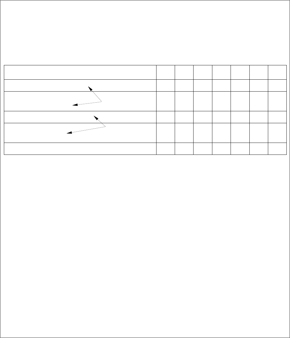
Requirements/Location 1234567
Nozzle "316 X X
Extern. optical centering
Head camera
222
6666
Transport direction left X X X X
Feeder "S_LIN_30"
Feeder "S_G_24N" X X
XXXX
Tracks still available 90 6 1 120 0 120 120
requirement through the
GF description
requirement through the
restrictions (.ri/.rs)