00191413-01.pdf - 第472页
14 Control / Cont rol Modules User Manual Line Computer UNIX 14.3 Station Controll ers Software Version 501.xx 01/99 Issue 14 - 36 14.3.4. 1 Display Area The indiv idual se ctions o f this area contai n the foll owing in…
User Manual Line Computer UNIX 14 Control / Control Modules
Software Version 501.xx 01/99 Issue 14.3 Station Controllers
14 - 35
14.3.4 Main Display Window of the Station controller
The various elements of the main display window and their tasks are described in the following.
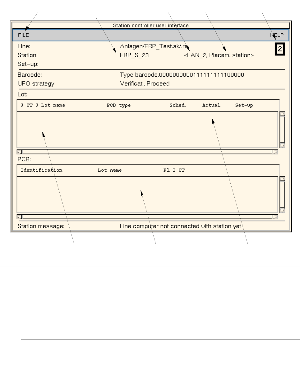
Fig. 14.3.1 Main Window "Station Controller"
The main display window is subdivided as follows:
- Menu bar
The menu bar contains the menus "FILE" and "HELP".
NOTE
Since the functions and operation of the menus "FILE" and "HELP" are similar to those in other
application programs of the line computer, they described in detail in chapt. 2.
- Display Area
menu bar
listing of the scheduled lots
IEC bus address
logic name
type of station
of station
listing of the currently
processed (scheduled) PCBs
Station number
display area
14 Control / Control Modules User Manual Line Computer UNIX
14.3 Station Controllers Software Version 501.xx 01/99 Issue
14 - 36
14.3.4.1 Display Area
The individual sections of this area contain the following information:
- Anlage: name of the line (incl. pathname)
(e.g. Anlagen/ERP_Test.ak/.ra)
- Station: logic name of the station, IEC bus address and type of station
(e.g. ERP_S_23 < LAN_2, Placem. station >)
- Set-up: set-up name (e.g. SWT_all01.ar)
- Barcode: type of barcode strategy (type and filter)
- UFO-Strategie: type of UFO strategy (e.g. Verificat., Proceed)
- Lot: This area containing a listing of the scheduled lots.
The job currently being processed is identified by an "a"
in the first column..
- PCB: This area containing a listing of the currently processed
(scheduled) PCBs
Identification: If barcode strategy "with barcode" is selected, the barcode no.
is displayed in the "identification" column.
(in the case of barcode strategy "without barcode, the field
remains empty)
- Station message: status of station
(e.g. "Line computer not connected with station yet")
User Manual Line Computer UNIX 14 Control / Control Modules
Software Version 501.xx 01/99 Issue 14.4 Set-Up Modification Generator
14 - 37
14.4 Set-Up Modification Generator
The principal task of the Set-Up Modification Generator is the display of set-ups, the creation of changeover
instructions and the creation of follow-up set-ups required in the production of given PCB types.
An SMD production line uses a sequence of different set-ups in the assembly of PCBs. The set-up data required
are held in the master data storage. The actual physical changeover procedure is carried out by the operator.
The user interface of the Set-up Modification Generator provides the required displays of set-ups and
changeover instructions (see Fig. 14.4.2), or else these can be output to the printer.
A request for set-up changeover can be initiated as follows:
- by the station controller, for the particular station it controls, at the moment changeover is actually to
be performed at the station.
- by the operator via the user interface of the Set-up Modification Generator, for the entire line, at any
time.
- by the Data Manager for the entire line, at any time.
14.4.1 Terms Used in the Connection With Set-Ups (Set-Up Types)
• Initial Set-Up
This refers to the set-up from which the changeover procedure originates.
In the case of changeover requests released by the station controller or the Data Manager the initial
set-up is always the current set-up of the station or the line.
• Follow-Up Set-Up
This refers to the set-up of a line or a station that is to be the result of the changeover procedure. The
follow-up set-up can be a set-up already existing or one to be newly created by the Set-Up Modification
Generator for the production of a specific PCB type.
• Target Set-Up
This is an existing set-up for a given PCB.
When a follow-up set-up for this PCB type is to be created, the target set-up specifies where the
components are to be set up that are not contained in the initial set-up. All components required for the
production of the PCB type must be contained in the target set-up.
• Changeover Instructions
They describe the changeover from an intitial set-up to a follow-up set-up.