00191413-01.pdf - 第534页
17.2 From the Placement Pro g ram to the Assembly User Manual Line Computer UNIX 17.2.1 Overview Software Version 501.xx 01/99 Issue 17 - 2 17.2 From the Placement Program to the Assembly 17.2.1 Ov erview Set-up generati…
User Manual Line Computer UNIX 17.1 Introduction
Software Version 501.xx 01/99 Issue
17 - 1
Usin
g
three PCBs as an example, this chapter contains a description of all work steps re
q
uired - from the
g
e-
neration of the placement pro
g
rams throu
g
h to
j
ob schedulin
g
.
This chapter can be used as a be
g
inner´s
g
uide for the new operator and be worked throu
g
h step-b
y
-step, or
it can serve as a reference or a refresher section for experienced pro
g
rammers. All this is accomplished b
y
the
two-pa
g
e concept with the left side containin
g
onl
y
ke
y
words and the ri
g
ht side describin
g
each work step in
detail.
The chapter is intended as a supplement to the other chapters of the User´s Manual and therefore cannot an-
ticipate ever
y
possible circumstance that ma
y
be of interest. For further information about a topic or a function,
please refer to the correspondin
g
chapter in the User´s Manual.
In addition, it is ver
y
helpful to use the On-Line Help s
y
stems available:
—
On-line Bubble-Help:
contains information about all editin
g
fields, icons and window areas.
• Click on the
Online Help On/Off
option on the
HELP
menu.
• Move the mouse pointer to the location where
y
ou wish to obtain explanations.
A window containin
g
the Help information is opened and closed a
g
ain b
y
movin
g
the mouse pointer.
—
Help Index:
contains a description on how to proceed concernin
g
almost all topics.
• Click on the
Index
option on the
HELP
menu.
The Help Index is opened.
• Search for a topic usin
g
the
Text search
function, or browse throu
g
h the contents and descriptions on
the topics b
y
clickin
g
on the terms hi
g
hli
g
hted in
g
reen.
The PCBs described relate to different learnin
g
ob
j
ectives:
•PCB 1: sin
g
le circuit, with focus on the basic principle of the
g
eneration of placement pro
g
rams;
•PCB 2: sin
g
le circuit, with focus on the description of customer-specific packa
g
e forms;
• PCB 3: complex circuit, with focus on cluster techni
q
ue.
All examples are based on a
g
iven line and station confi
g
uration. Since the confi
g
uration differs from customer
to customer, the data
g
iven can be used as an example onl
y
and must be adapted b
y
the customers to satisf
y
their individual re
q
uirements.
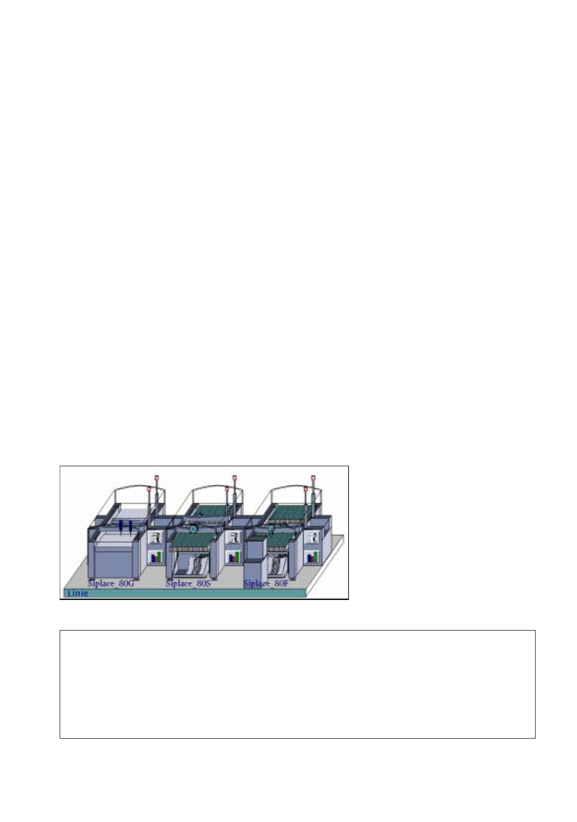
Station Configuration
17. Practical Tips on Using the LC UNIX
17.1 Introduction
Siplace_80G :
• optical PCB centerin
g
Siplace_80S:
• optical PCB centerin
g
• revolver head
•se
g
ment t
y
pe 2 -> 6xx nozzles
• component camera 19x25 in head
-> sensor t
y
pe 9
Siplace_80F:
• optical PCB centerin
g
• IC-head -> 4xx nozzles
• IC-head camera -> sensor t
y
pe 7
• revolver head
•se
g
ment t
y
pe 2 -> 6xx nozzles
• component camera 19x25 in head
-> sensor t
y
pe 9
• Waffle-Pack Chan
g
er
Line Configuration
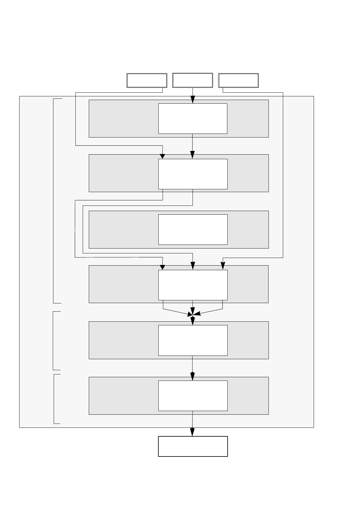
17.2 From the Placement Pro
g
ram to the Assembly User Manual Line Computer UNIX
17.2.1 Overview Software Version 501.xx 01/99 Issue
17 - 2
17.2 From the Placement Program to the Assembly
17.2.1 Overview
Set-up generation
Section 17.2.6
Line Control
Section 17.2.7
Component
description
Section 17.2.3
Package form (GF)
description
Section 17.2.2
PCB
description
Section 17.2.5
Adhesive pattern
description
Section 17.2.4
PCB 1 PCB 3
Assembly
Creation of a placement program
Generation of a
Scheduling a job
Package Form Editor
Desktop
Component Editor
Adhesive Pattern
Editor
PCB Editor
Optimization dialog
Job Control
PCB 2
set-up
User Manual Line Computer UNIX 17.2 From the Placement Pro
g
ram to the Assembly
Software Version 501.xx 01/99 Issue 17.2.1 Overview
17 - 3
The adhesive pattern description is dispensed with.
Package Form Editor
Component Editor
PCB Editor
Optimization Dialog
Job Control
Adhesive Pattern Editor