00191413-01.pdf - 第594页
17.5 Line Control User Manual Line Computer UNIX 17.4.3 Manual Set-Up Adjustment S oftware Version 501.xx 01/99 Issue 17 - 62 17.5 Line Control The three P CBs can now be p roduced us in g the created set-up. Openin g Jo…
User Manual Line Computer UNIX 17.4 Set-Up Generation
Software Version 501.xx 01/99 Issue 17.4.3 Manual Set-Up Adjustment
17 - 61
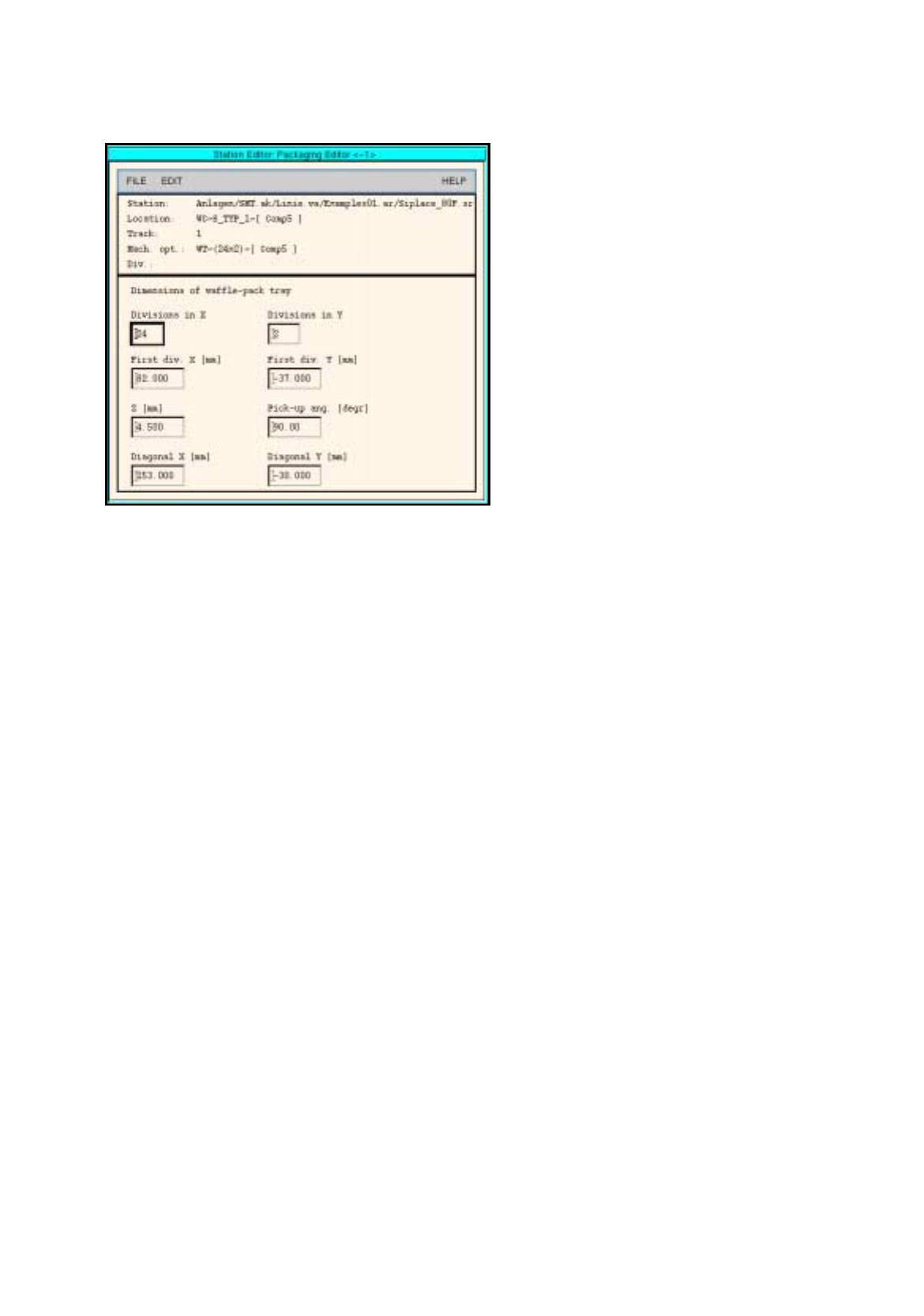
Fig. 17.4.1 Definition of a Waffle-Pack Tray
47. Click on the
Quit
option on the
FILE
menu.
The Packa
g
in
g
Editor is closed. The pick-up area of the waffle-pack tra
y
is displa
y
ed to
g
ether with the
indicated spacin
g
.
To allocate a component to a waffle-pack tray, proceed as follows:
48. On the component list click on the component, here:
Comp5
.
49. Click on the blue pick-up area of the waffle-pack tra
y
.
The component is allocated to the compartments of the waffle-pack tra
y
.
To save the set-up, proceed as follows:
50. Click on the
Save
option on the
FILE
menu.
The created set-up is saved.
51. Click on the
Quit
option on the
FILE
menu.
The Set-Up Editor/WPC Editor is closed.
To adjust the conveyor width (if not already done), proceed as follows:
52. On the desktop click on the
Line control
option on the
SERVICES
menu.
The Line control window is opened.
53. Click on the
Conveyor width
button.
A dialo
g
box is opened.
54. Activate the
Width adj. upon cluster change
button.
With this function, the conve
y
or width is ad
j
usted automaticall
y
upon the next cluster chan
g
e.
55. Click on the
OK
button.
The dialo
g
box is closed.
56. Click on the
Quit
option on the
FILE
menu.
The Line control window is closed.
17.5 Line Control User Manual Line Computer UNIX
17.4.3 Manual Set-Up Adjustment Software Version 501.xx 01/99 Issue
17 - 62
17.5 Line Control
The three PCBs can now be produced usin
g
the created set-up.
Opening Job Control
Scheduling a job
Displaying and printing
set-up changeover in-
structions
Changing the set-up of
stations and confirming
set-up changeover
Inserting jobs in the job
list
The placement of the
scheduled jobs is
started.
User Manual Line Computer UNIX 17.5 Line Control
Software Version 501.xx 01/99 Issue 17.4.3 Manual Set-Up Adjustment
17 - 63
To open Job Control, proceed as follows:
1. On the desktop, click on the Job icon.
Job Control is opened.
To insert jobs in the job list, proceed as follows:
2. Activate the Create icon .
3. Activate the Edit support icon .
The Edit support Job Data is opened.
4. Successivel
y
select the followin
g
data b
y
double-clickin
g
: the PCB, here:
Example_1.la,
the line, here:
SMT.ak
, the subline, here:
Linie.va
and the set-up, here:
Examples01.ar
.
The Edit support Job Data is closed, return to Job Control.
The selected data now appear in the editin
g
area below the
j
ob list.
5. In the editin
g
area click on the
Lot name
field and enter the lot name, here:
ex1
.
6. In the editin
g
area click on the
Lot size
field and enter the lot size of the
j
ob, here:
10
.
7. In the editin
g
area click on the
Lot type
field and enter the lot t
y
pe, here:
F
.
8. Click on the
OK
button.
The
j
ob is transferred to the
j
ob list. In the case of fault
y
entries, the field concerned is surrounded b
y
a
red frame and an error messa
g
e is displa
y
ed above the
j
ob list. Correct the entr
y
.
9. Insert the remainin
g
PCBs analo
g
ousl
y
, here:
Example_2.la
and
Example_3.la
, see chart.
To schedule a job, proceed as follows:
10. Click on the
Schedule
icon .
On the
j
ob list successivel
y
click on the individual
j
obs.
The
j
obs are checked for producibilit
y
and then passed to the station controller after the successful com-
pletion of the producibilit
y
check.
The Set-up Modification Generator is opened.
If errors are encountered durin
g
the producibilit
y
check, the status of the lot file is indicated b
y
means of
an
E
(
Error
)
. In the case of an error, proceed as follows:
— Click on the fault
y
j
ob.
The
j
ob is hi
g
hli
g
hted.
— Click on the
Error messages...
option on the
SERVICES
menu.
The File displa
y
containin
g
the error messa
g
es is displa
y
ed.
— Correct the errors displa
y
ed.
— Schedule the
j
ob once a
g
ain.
To display and print out set-up changeover instructions:
11. In the Set-Up Modification Generator activate the
Set-up modification instructions
button.
The set-up chan
g
eover instructions are displa
y
ed.
12. On the
FILE
menu click on the
Print
command, then
Print Line
.
The set-up is printed out for all stations.
To change the set-up of stations and to confirm the changeover, proceed as follows:
13. Chan
g
e the set-up of the stations in accordance with the set-up chan
g
eover instructions.
14. Once the set-up of the stations has been chan
g
ed over, select the individual stations in the selection field
and click on the
Set-up modified
button for each station.
The
j
ob is onl
y
scheduled and placement is started, when the set-up chan
g
eover of all stations has been
completed.
The Set-Up Modification Generator is closed.
The assembl
y
of the PCBs is started.
PCB Lot name Lot size
Lot
type
Example_1.la ex1 10 F
Example_2.la ex2 13 F
Example_2.la ex3 16 F