00195941-03-UM SiplaceCA-EN.pdf - 第101页
User Manual SIPLACE CA 2 Operational Safety Edition 08/2011 EN 2.10 Disabling the Compre ssed Air Supply and Discharging the Pressure 101 2.10 Disabling the Compressed Air Supply and Dis- charging the Pressure The operat…
2 Operational Safety User Manual SIPLACE CA
2.9 Residual Voltages and Discharge Times Edition 08/2011 EN
100
2.9.1.2 Residual Voltages and Discharge Times after Switching off at the Main Switch
2
CAUTION 2
To avoid losing data, assess the following criteria before switching off your automatic placement
system (apart from in emergencies):
– Has the placement system finished transmitting machine, setup and panel data?
– Has the placement system finished processing the PCB?
– Has the placement system completed the run-up phase?
Pins X11, X13_1 and X13_4
measured to X12 (GND)
Residual voltages when
main power switch is off Discharge times
X11 < 10 VDC < 7 s
X13_1 < 10 VDC < 50 s
X13_4 < 10 VDC < 2 s

User Manual SIPLACE CA 2 Operational Safety
Edition 08/2011 EN 2.10 Disabling the Compressed Air Supply and Discharging the Pressure
101
2.10 Disabling the Compressed Air Supply and Dis-
charging the Pressure
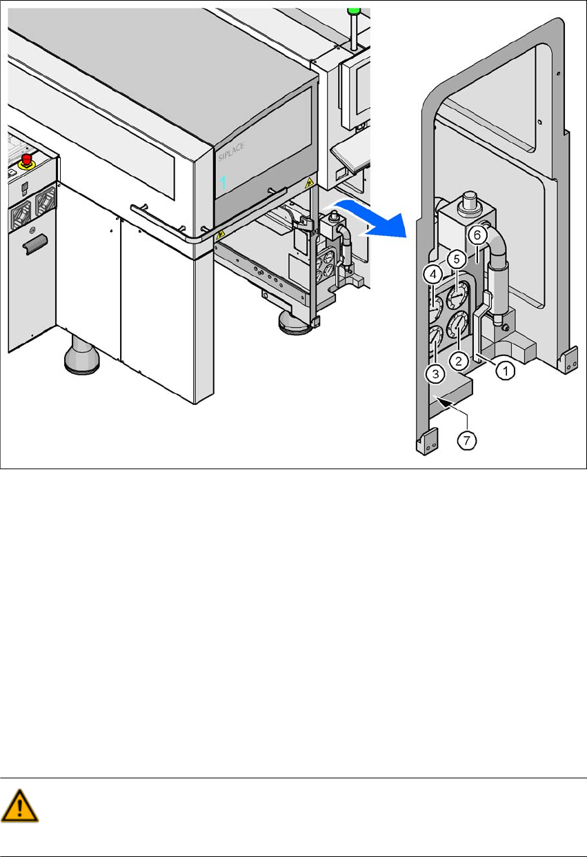
The operating pressure of the machine and SWS is fixed to ± 0.025 MPa (5.0 ± 0.25 bar). The
position of the compressed air unit is shown by item 1 of the fig. 2.10 - 1
. You can interrupt the
flow of compressed air to the machine with the shutoff valve (item 2 of the fig. 2.10 - 1
).
The SWS is supplied with compressed air via the machine.
Use the machine key to release the cover lock.
Lift the cover (see fig. 2.10 - 1).
Turn the handle of the shutoff valve (item 1 of the fig. 2.10 - 1) from vertical to horizontal po-
sition.
Observe the operating pressure manometer (item 5 of the fig. 2.10 - 1). When the automatic
placement system is switched on, the pressure discharges to 0 MPa (0 bar) within 1 minute.
CAUTION
When the machine is switched on, do not use the stop valve to interrupt the compressed air sup-
ply for more than 30 minutes. If you need to shut off the pneumatic system for longer in order to
carry out preventive maintenance or servicing work, you must switch the placement system off at
the main switch and disconnect it from the power supply.
2 Operational Safety User Manual SIPLACE CA
2.10 Disabling the Compressed Air Supply and Discharging the Pressure Edition 08/2011 EN
102
Fig. 2.10 - 1 Compressed air unit on the placement system
(1) Shutoff valve
(2) Manometer for the machine component supply pressure
Target pressure: 0.48 ± 0.025 MPa, 4.8 ± 0.25 bar (display range 0 - 0.6 MPa, 0 - 6 bar)
(3) Manometer for the gantry distributor supply pressure
Target pressure: 0.46 ± 0.01 MPa, 4.6 ± 0.1 bar (display range 0 - 0.6 MPa, 0 - 6 bar)
(4) Manometer for the bulkcase feeder supply pressure
Target pressure: 0.25 ± 0.05 MPa, 2.5 ± 0.5 bar (display range: 0 - 0.6 MPa, 0 - 6 bar)
(5) Manometer for input pressure
Target pressure: 0.5 - 1.0 MPa, 5 - 10 bar (display range: 0 - 1.0 MPa, 0 - 10 bar)
(6) Compressed air filter
(7) Hexagon socket-head screw for fixing the pneumatic unit
WARNING
NEVER detach compressed air lines while they are still pressurized. Risk of injury. 2