00195941-03-UM SiplaceCA-EN.pdf - 第103页
User Manual SIPLACE CA 2 Operational Safety Edition 08/2011 EN 2.11 Energy State after Switching Off at the Main Switch 103 2 Fig. 2.10 - 2 Electrical and pneumatic al connection point at the SWS 2 2.1 1 Energy S t ate a…
2 Operational Safety User Manual SIPLACE CA
2.10 Disabling the Compressed Air Supply and Discharging the Pressure Edition 08/2011 EN
102
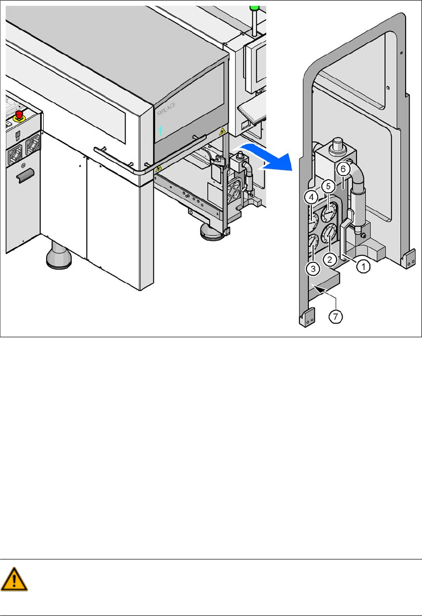
Fig. 2.10 - 1 Compressed air unit on the placement system
(1) Shutoff valve
(2) Manometer for the machine component supply pressure
Target pressure: 0.48 ± 0.025 MPa, 4.8 ± 0.25 bar (display range 0 - 0.6 MPa, 0 - 6 bar)
(3) Manometer for the gantry distributor supply pressure
Target pressure: 0.46 ± 0.01 MPa, 4.6 ± 0.1 bar (display range 0 - 0.6 MPa, 0 - 6 bar)
(4) Manometer for the bulkcase feeder supply pressure
Target pressure: 0.25 ± 0.05 MPa, 2.5 ± 0.5 bar (display range: 0 - 0.6 MPa, 0 - 6 bar)
(5) Manometer for input pressure
Target pressure: 0.5 - 1.0 MPa, 5 - 10 bar (display range: 0 - 1.0 MPa, 0 - 10 bar)
(6) Compressed air filter
(7) Hexagon socket-head screw for fixing the pneumatic unit
WARNING
NEVER detach compressed air lines while they are still pressurized. Risk of injury. 2
User Manual SIPLACE CA 2 Operational Safety
Edition 08/2011 EN 2.11 Energy State after Switching Off at the Main Switch
103
2
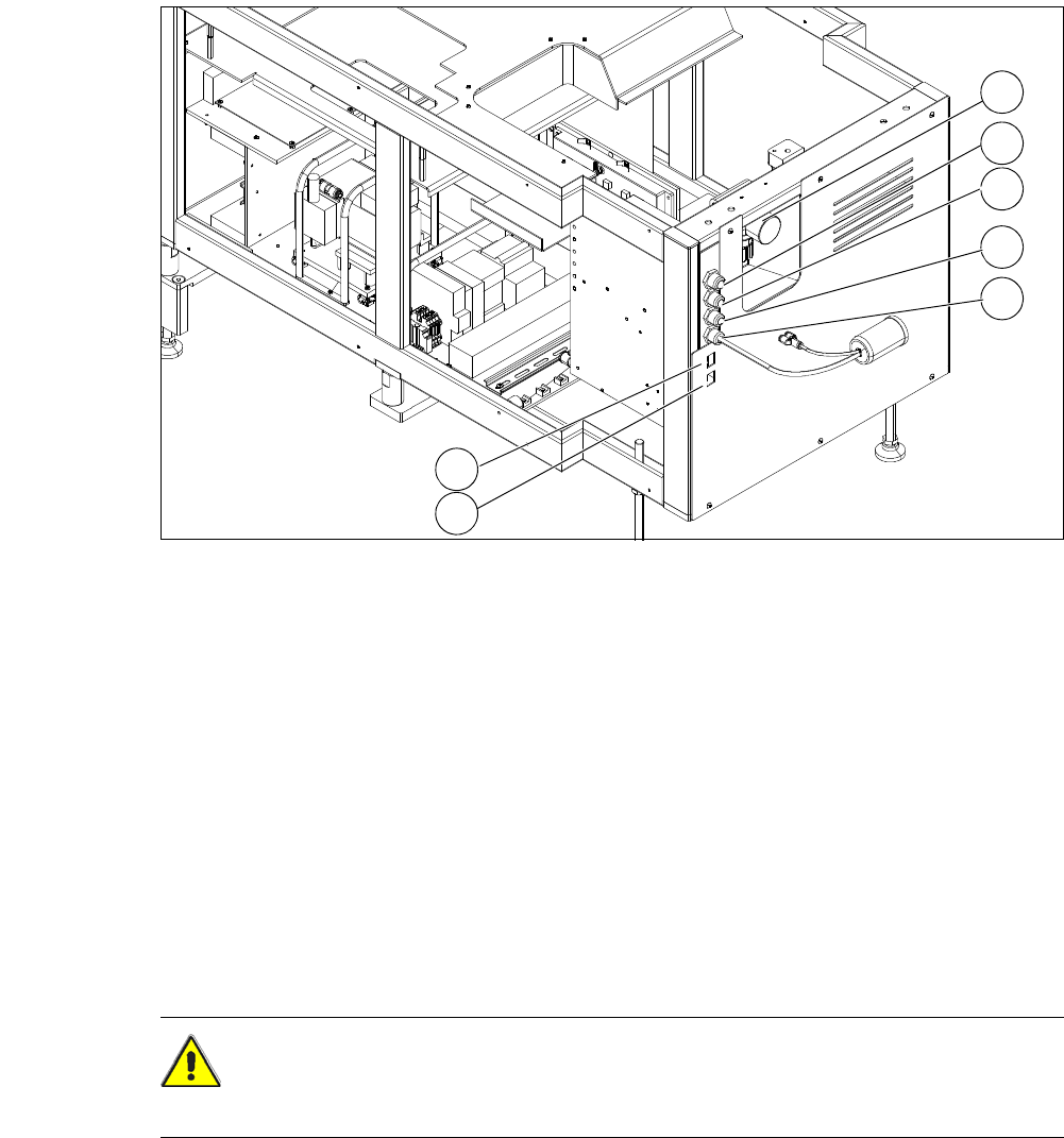
Fig. 2.10 - 2 Electrical and pneumatical connection point at the SWS
2
2.11 Energy State after Switching Off at the Main Switch
CAUTION 2
Please note that each SWS module has its own main switch.
(1) Manometer for compressed air supply (2) Voltage supply
(3) Communication with SIPLACE machine (4) CAN bus
(5) Compressed air connection (modified
adapter dummy connector [03011592-01])
(6) LAN1
(7) LAN2
2
1
3
4
5
6
7
2 Operational Safety User Manual SIPLACE CA
2.11 Energy State after Switching Off at the Main Switch Edition 08/2011 EN
104
2.11.1 Main Switch on Placement Machine
2
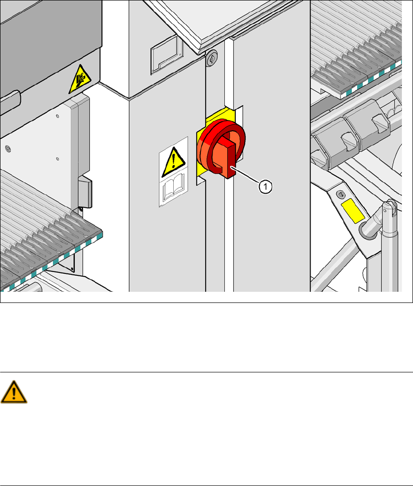
Fig. 2.11 - 1 Position of the power supply on the machine
2
WARNING
The placement system is supplied with 3 x 208 VAC, 3 x 230 VAC, 3 x 380 VAC, 3 x 400 VAC or
3x415VAC ± 5%, 50/60Hz mains voltage. This means that some parts of the system carry po-
tentially lethal voltages - even when switched off at the main power switch. Incorrect handling of
the placement system can therefore result in death or severe injury or considerable damage to
equipment. 2
Always follow the applicable accident prevention and DIN regulations (particularly DIN EN 60
204, part 1).
The guard over the power supply unit must ONLY be opened by appropriately qualified and
trained personnel.
(1) Main switch