00195941-03-UM SiplaceCA-EN.pdf - 第106页
2 Operational Safety User Manual SIPLACE CA 2.11 Energy State after Switching Off at the Main Switch Edition 08/2011 EN 106 2 Fig. 2.1 1 - 3 Posit ion of the computer unit (1) Compu ter unit (top part) (2) Position of th…
User Manual SIPLACE CA 2 Operational Safety
Edition 08/2011 EN 2.11 Energy State after Switching Off at the Main Switch
105
2
Fig. 2.11 - 2 Position of main power switch and service socket
(1) Main switch
(2) Service socket
2 Operational Safety User Manual SIPLACE CA
2.11 Energy State after Switching Off at the Main Switch Edition 08/2011 EN
106
2
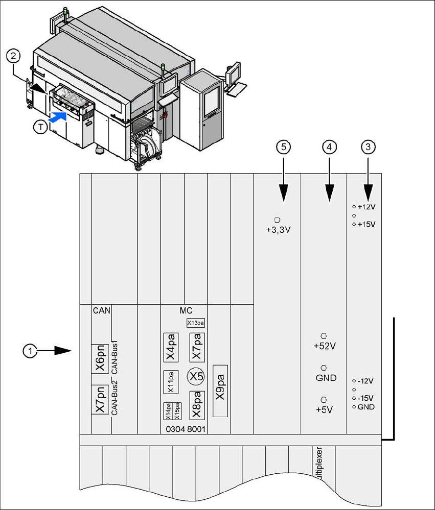
Fig. 2.11 - 3 Position of the computer unit
(1) Computer unit (top part)
(2) Position of the computer unit
(3) Power supply unit ± 12 V-/± 15 V-
(4) Power supply unit ± 5 V-/± 52 V-
(5) Power supply unit + 3.3V-
(T) Direction of PCB transport

User Manual SIPLACE CA 2 Operational Safety
Edition 08/2011 EN 2.11 Energy State after Switching Off at the Main Switch
107
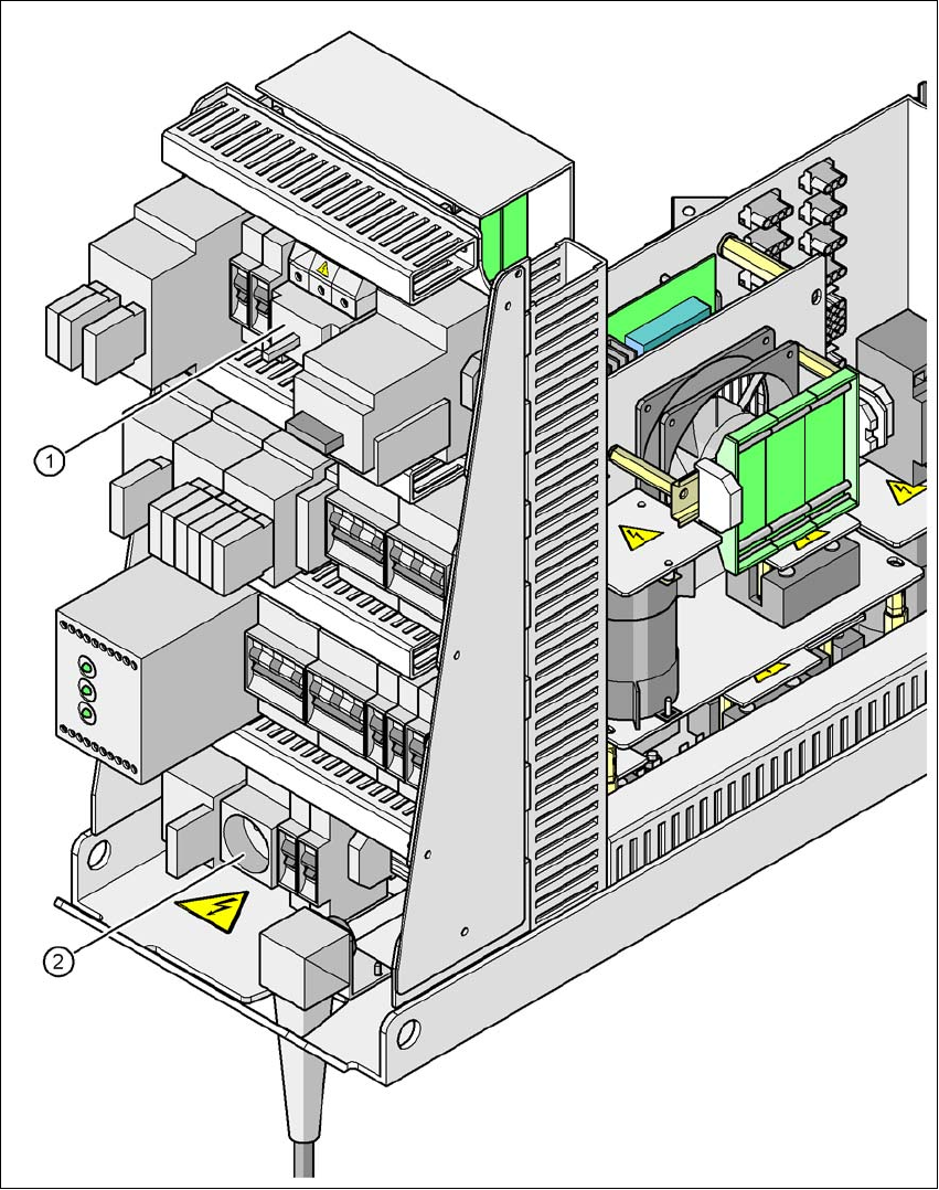
2.11.1.1 Placement System Switched off at the Main Switch, But Still Connected ...
WARNING
The following components still carry potentially lethal voltages even if the main power switch is
switched off:
– Cable connection terminals L1, L2, and L3 of the Q1 main power switch (see fig. 2.11 - 4
)
– Service socket X102 (see fig. 2.11 - 4
)
– Automatic circuit breaker F1 for the service socket (see fig. 2.11 - 4
)
– Z1 line filter (see fig. 2.11 - 5
)
– Discharge inductor L20 with fuses F21, F22 and F23 (see fig. 2.11 - 5
)
– Terminal block X100 for connection of main power supply cable (see fig. 2.11 - 5
)
– The color of all individual wires, which still carry potentially lethal voltages even if the main
power switch is switched off, is brown.
– Axis unit