00195941-03-UM SiplaceCA-EN.pdf - 第113页
User Manual SIPLACE CA 2 Operational Safety Edition 08/2011 EN 2.12 Lock Out and Tag Out Procedure 113 2 Fig. 2.12 - 1 Position of the motor contactor 2 (1) Power Su pply (2) Motor cont actor (T) Direction of PCB transpo…
2 Operational Safety User Manual SIPLACE CA
2.12 Lock Out and Tag Out Procedure Edition 08/2011 EN
112
2.12.2 Description
Whenever it becomes necessary to isolate, control and release energy, the following procedure is
to be followed
Notify affected employees.
Shut down the equipment. Carry out all normal stopping procedures:
– Press the Stop button.
– Shut down the control computer.
– Switch the placement machine off at the main power switch.
Isolate the machine from all its energy sources:
– Shut off the compressed air supply
– Shut off the main power supply
Lock the machine, including the SWS.
– Attach a lock whenever possible, e.g. to the motor contactor.
User Manual SIPLACE CA 2 Operational Safety
Edition 08/2011 EN 2.12 Lock Out and Tag Out Procedure
113
2
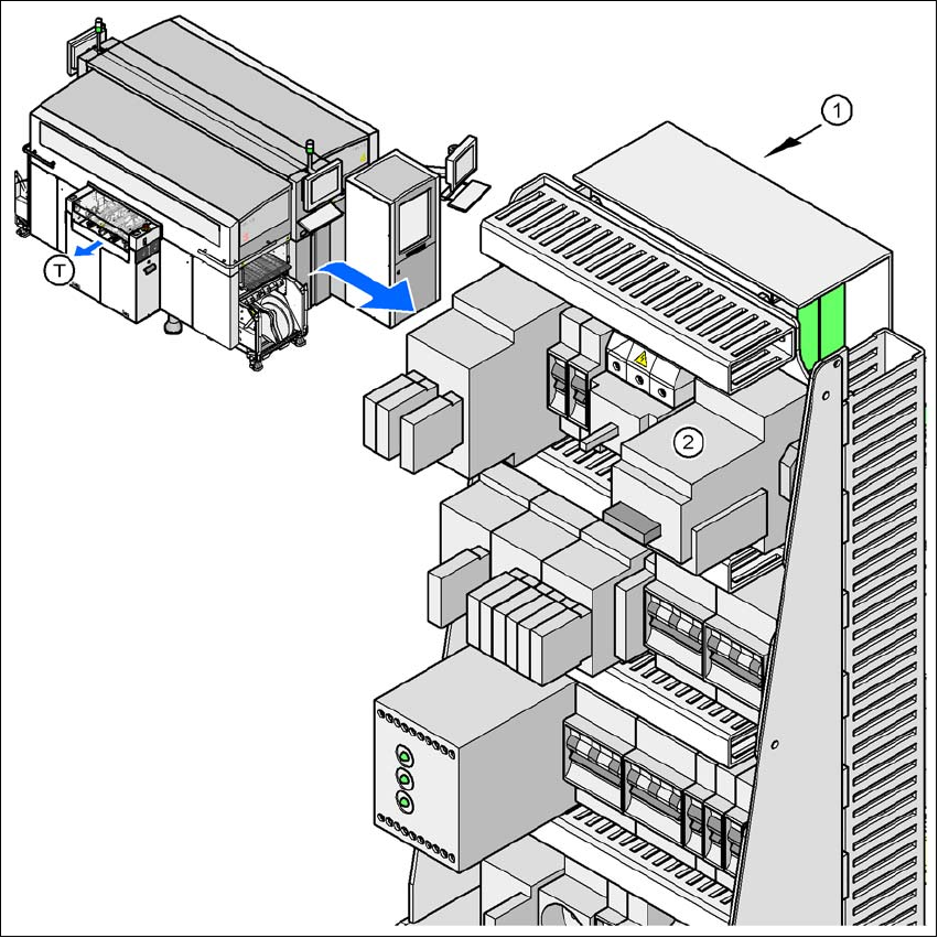
Fig. 2.12 - 1 Position of the motor contactor
2
(1) Power Supply
(2) Motor contactor
(T) Direction of PCB transport
2 Operational Safety User Manual SIPLACE CA
2.12 Lock Out and Tag Out Procedure Edition 08/2011 EN
114
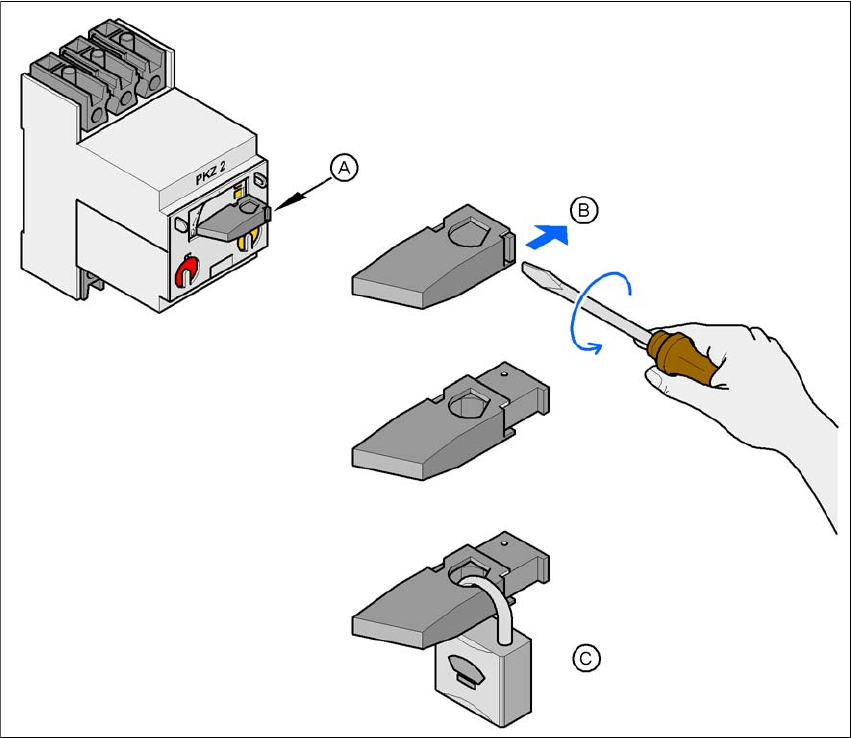
Fig. 2.12 - 2 Locking the motor contactor
2
– Alternatively: tag out alternative
If a machine can be locked out, it must be. However, there are situations where energy iso-
lating devices cannot accommodate locks. In these cases, the energy isolating devices must
be tagged to warn employees that the machine is de-energized for servicing. The tag must
be securely fastened, it must be placed in a position visible to all and it may only be removed
by the person who attached it. 2
(A) Turn the operating lever counterclockwise.
(B) Use the screwdriver to push the locking lug out of the operating lever.
(C) Secure the operating lever with a padlock.