00195941-03-UM SiplaceCA-EN.pdf - 第121页
User Manual SIPLACE CA 3 Technical Data Edition 08/2011 EN 3.1 SIPLACE CA Performance Data 121 3 T echni cal Data Flip Chip Die Att ach X/Y accura cy a a) Calculated with glass die on glass plate - SIPLACE MAC test ± 10 …
3 Technical Data User Manual SIPLACE CA
3.1 SIPLACE CA Performance Data Edition 08/2011 EN
120
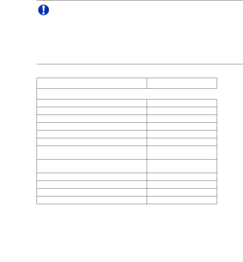
NOTE 3
The following table lists the benchmark values (as defined in "Scope of Service and Delivery
SIPLACE CA") for SMT placement in each placement area. As the benchmark test for the Twin-
Head and the C&P heads uses different components, the benchmark values for the TwinHead
and C&P heads must be specified separately. However, the joint component spectrum can still
be processed by both the TwinHead and the Collect&Place heads in the same production envi-
ronment.
Die placement depends on several process-specific parameters. The expected throughput can be
individually calculated on request.
The benchmark values for one SWS and a die size of 1x1 mm are:
In “Flip Chip” mode: 9,000 dies / h without flux dipping 3
In “Flip Chip” mode: 6,000 dies / h with flux dipping 3
In “Die Attach” mode (on request): 6.000 dies / h 3
Placement heads in placement area (PA) Placement rate [comp./h]
SMD Application
C&P20CA and C&P20CA 40,000 cph ± 3 %
C&P12 and C&P12 26,400 cph ± 3 %
C&P12 and C&P6 20,300 cph ± 3 %
C&P6 and C&P12 20,300 cph ± 3 %
C&P6 and C&P6 18,300 cph ± 3 %
TH and TH 5,800 cph ± 3 %
C&P12 and TH C&P12: 14,000 cph ± 3 %
TH: 3,300 cph ± 3 %
C&P6 and TH C&P6: 9,800 cph ± 3 %
TH: 3,300 cph ± 3 %
C&P20CA 20,000 cph ± 3 %
C&P12 14,000 cph ± 3 %
C&P6 9,800 cph ± 3 %
TH 3,700 cph ± 3 %

User Manual SIPLACE CA 3 Technical Data
Edition 08/2011 EN 3.1 SIPLACE CA Performance Data
121
3
Technical Data Flip Chip Die Attach
X/Y accuracy
a
a) Calculated with glass die on glass plate - SIPLACE MAC test
± 10 µm at 3 ± 10 µm at 3
Placement performance (IPC)
b
b) Calculated with the SIPLACE CP20-CA head
9,000 dies/h
(without flux dipping)
6.000 dies / h
6,000 dies/h
(with flux dipping)
Die sizes
c
c) Calculated with the SIPLACE CP20 and CP12 head. Alternative SIPLACE placement
heads available for greater component spectrum.
0.8 mm to 18.7 mm 0.8 mm to 18.7 mm
Minimum die thickness (silicium) 50 µm 50 µm
Minimum bump size 50 µm n/a
Minimum bump grid 100 µm n/a
SIPLACE Wafer System SWS Horizontal system, automatic wafer change,
MCM
SWS wafer size 4“ to 12“
Waferframe 12“/8“
Waferframe area 0 mm to 8 mm
Die Ejection System Programmable ejection speed
Linear Dipping Unit LDU Individually programmable speed
Flux viscosity 3,000 to 100,000 cPs
Accuracy of flux height ± 5 µm
Programmable set-down force 1.0 N to 5.0N (depends on head)
Substrate types FR4, ceramic, flex, boats, 8"/12" wafer etc.
Substrate thickness 0.3 mm to 4.5 mm
Substrate size 50 mm x 50 mm to 508 mm x 610 mm

3 Technical Data User Manual SIPLACE CA
3.1 SIPLACE CA Performance Data Edition 08/2011 EN
122
3
Placement head
types-
– 20 segment Collect&Place CA head (C&P20CA)
– 12 segment Collect&Place CA head (C&P12A)
– 6 segment Collect&Place CA head (C&P6)
– SIPLACE TwinHead (TH)
(only possible in a placement area without SWS).
Number of gan-
tries
CA4: 4 gantries
CA3: 3 gantries
Place-
ment-positions
6,000 / gantry for the Collect&Place heads
2,000 / gantry for the TwinHead
Component
spectrum
a
0,4 mm x 0,2 mm (01005), 0,6 mm x 0,3 mm (0201)
bis 85 mm x 85 mm / 125 mm x 10 mm,
max. 200 mm x 125 mm (with restrictions)
Component
height
C&P20CA: 4 mm
C&P12: 6 mm
C&P6: 8.5 mm
TH: 25 mm
b
(higher heights on request)
Placement
accuracy
(Standard--cri-
teria for SMD)
C&P20CA
C&P12
C&P6
TH
TH
± 41 µm (3), ± 55 µm (4)
± 41 µm (3), ± 55 µm (4)
± 45 µm (3 ), ± 60 µm (4 )
± 26 µm (3), ± 35 µm (4)
± 22 µm (3), ± 30 µm (4)
Component camera, type 41
(6 x 6)
Component camera, type 29
(27 x 27)
Component camera, type 29
(27 x 27)
Component camera, type 33
(55 x 45)
Component camera, type 25
(16 x 16)
Placement
accuracy
(Advanced cri-
teria for SWS)
C&P20CA
C&P12
C&P6
TH
TH
± 25 µm (3), ± 33 µm (4)
± 25 µm (3), ± 33 µm (4)
± 35 µm (3), ± 47 µm (4)
± 26 µm (3), ± 35 µm (4)
± 22 µm (3), ± 30 µm (4)
Component camera, type 41
(6 x 6)
Component camera, type 29
(27 x 27)
Component camera, type 29
(27 x 27)
Component camera, type 33
(55 x 45)
Component camera, type 25
(16 x 16)