00195941-03-UM SiplaceCA-EN.pdf - 第145页
User Manual SIPLACE CA 3 Technical Data Edition 08/2011 EN 3.5 Line Concept 145 The machine is equipped with both SIPL ACE wafe r systems and with changeover tab les and can therefore pr oduce the entire pr oduct with SM…
3 Technical Data User Manual SIPLACE CA
3.5 Line Concept Edition 08/2011 EN
144
3.5 Line Concept
3.5.1 Description
3
Flexibility, modularity, compact dimensions and high power density are the hallmarks of the new
SIPLACE concept. Operated together with the SIPLACE X-series, the SIPLACE CA machine al-
lows you to individually configure your production line with both identical and differing modules. If
the production requirements change, the individual placement machines are so compact and can
be combined with such flexibility that they can be recombined quickly and easily.
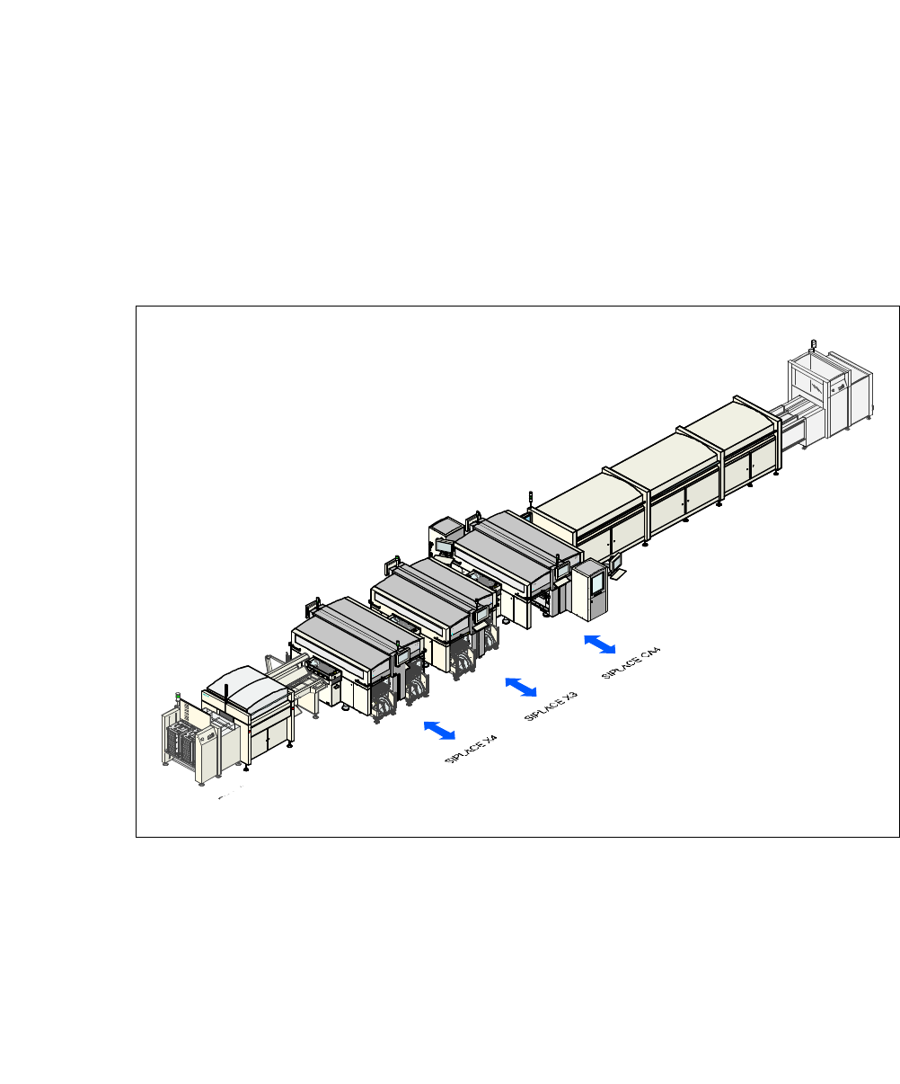
Fig. 3.5 - 1 Sample line concept
3
The SIPLACE family has the optimum placement system for each individual performance require-
ment.
SIPLACE machines from the CA series can place bare dies directly from the wafer, by using the
flip chip or die attach process, and can also place the entire SMT spectrum covered by the SI-
PLACE X machines. Thus, the SIPLACE CA is the beginning of a new placement technology
within the SIPLACE family.
I
n
p
u
t
s
t
a
t
i
o
n
S
c
r
e
e
n
p
r
i
n
t
e
r
S
o
l
d
e
r
i
n
g
f
u
r
n
a
c
e
Ou
t
p
u
t
s
t
a
t
i
o
n

User Manual SIPLACE CA 3 Technical Data
Edition 08/2011 EN 3.5 Line Concept
145
The machine is equipped with both SIPLACE wafer systems and with changeover tables and can
therefore produce the entire product with SMDs and bare dies, in one production cycle.
The SIPLACE CA even demonstrates a higher throughput performance than previous placement
systems for products which are only placed with bare dies.
Since this new concept combines at least two production lines to form a single lines (SMD and
bare die placement), the investment costs and cost of ownership can be reduced significantly.
In the medium term the customer can switch production from IC package placement to bare die
placement, in order to improve handling times, product costs and product dimensions.
3 Technical Data User Manual SIPLACE CA
3.6 Overview of Modules Edition 08/2011 EN
146
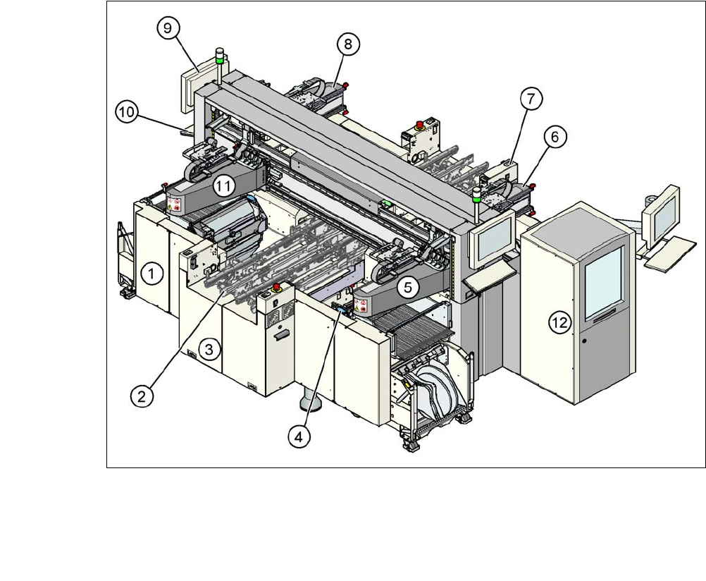
3.6 Overview of Modules
3.6.1 Overview of Modules in SIPLACE CA4
3
3
Fig. 3.6 - 1 CA4 machine with SWS - overview of modules
(1) Machine frame (2) PCB conveyor
(flexible dual conveyor)
(3) Extension kit on the PCB input side (4) Component trolley docking unit,
tape cutter, used tape channel
(5) Gantry 1 with placement head (6) Gantry 2 with placement head
(7) Extension kit on the PCB output side (8) Gantry 3 with placement head
(9) Monitor screen (2x) (10) Keyboard (2x)
(11) Gantry 4 with placement head (12)SIPLACE Wafer System (SWS) at location
2