00195941-03-UM SiplaceCA-EN.pdf - 第160页
3 Technical Data User Manual SIPLACE CA 3.7 SIPLACE Wafer System (SWS) Edition 08/2011 EN 160 3.7.5 Overview of Modules Fig. 3.7 - 12 Over view of the SWS 3 (1) Gripper (2) Flip unit (3) Install ation location for option…
User Manual SIPLACE CA 3 Technical Data
Edition 08/2011 EN 3.7 SIPLACE Wafer System (SWS)
159
3
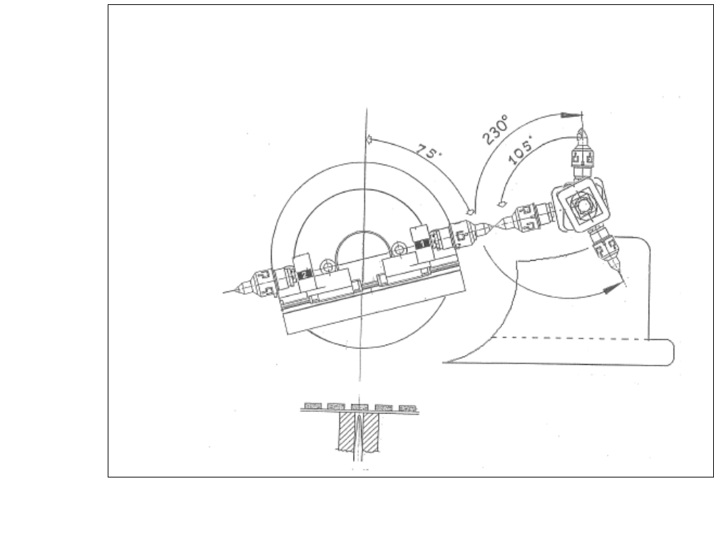
Fig. 3.7 - 11 Positions flip head/ Die attach segment
The transfer position of the flip head, the pick up and discharge position, as well as the transfer
position of the die attach segment to the placement head.
3 Technical Data User Manual SIPLACE CA
3.7 SIPLACE Wafer System (SWS) Edition 08/2011 EN
160
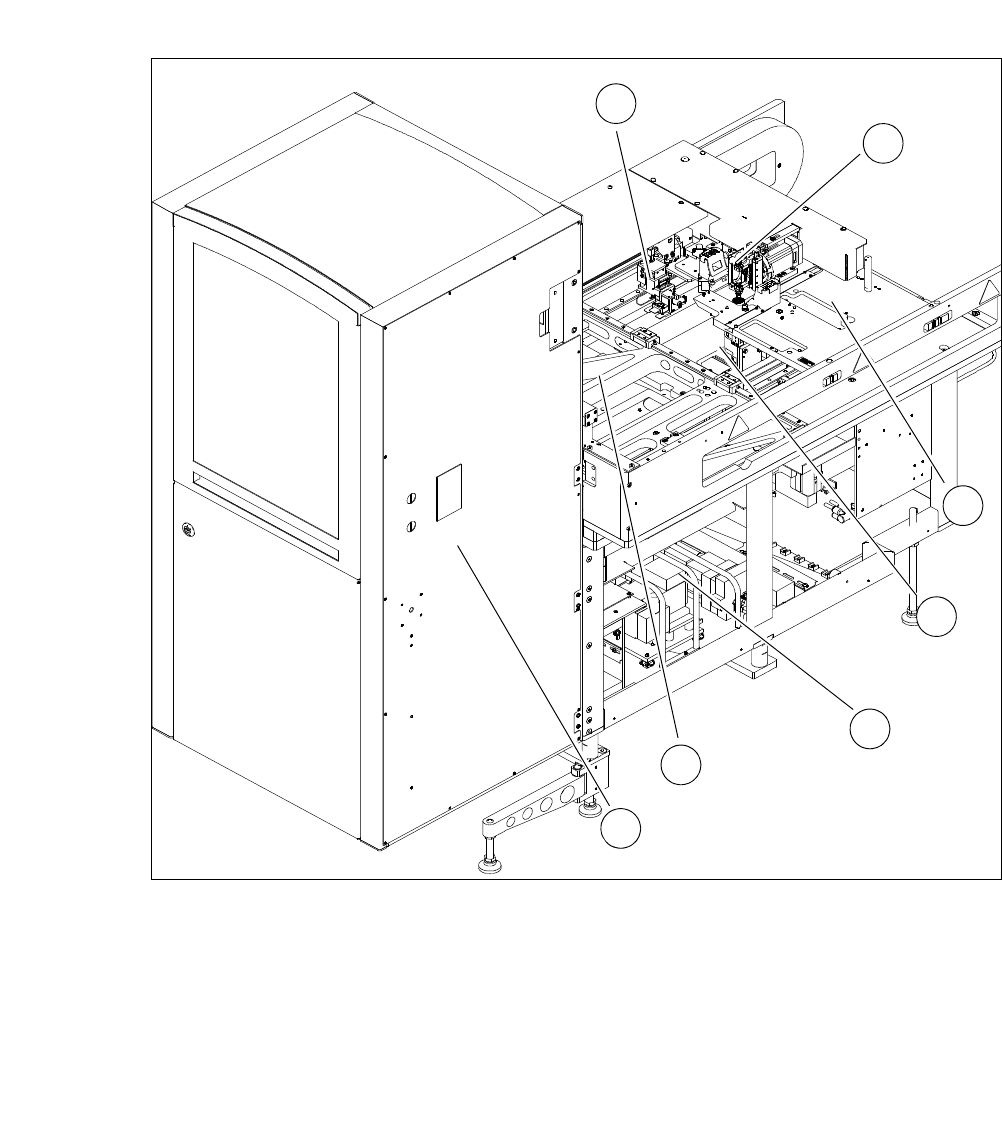
3.7.5 Overview of Modules
Fig. 3.7 - 12 Overview of the SWS
3
(1) Gripper (2) Flip unit
(3) Installation location for options (die attach
unit or linear dipping unit)
(4) Die ejector
(5) Supply unit (6) XY unit
(7) Magazine lift
1
2
3
4
5
6
7
User Manual SIPLACE CA 3 Technical Data
Edition 08/2011 EN 3.7 SIPLACE Wafer System (SWS)
161
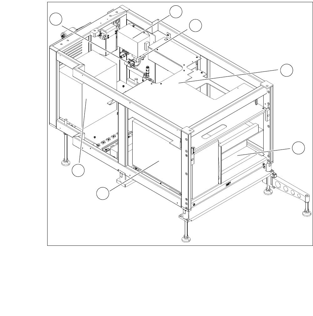
Fig. 3.7 - 13 Supply unit of the SWS front view
3
(1) Electronic unit front (2) Computer unit
(3) Transformer (4) Pressure switch
(5) Mains filter (6) Solenoid valve
(7) Cover
3
2
1
7
6
5
4