00195941-03-UM SiplaceCA-EN.pdf - 第164页
3 Technical Data User Manual SIPLACE CA 3.7 SIPLACE Wafer System (SWS) Edition 08/2011 EN 164 3.7.6.2 Flip Unit 3 Fig. 3.7 - 16 Flip unit 3 3 (1) Flip head (2) Nozzle or tool take-up 1 2 2
User Manual SIPLACE CA 3 Technical Data
Edition 08/2011 EN 3.7 SIPLACE Wafer System (SWS)
163
3.7.6 Description of the SWS Modules
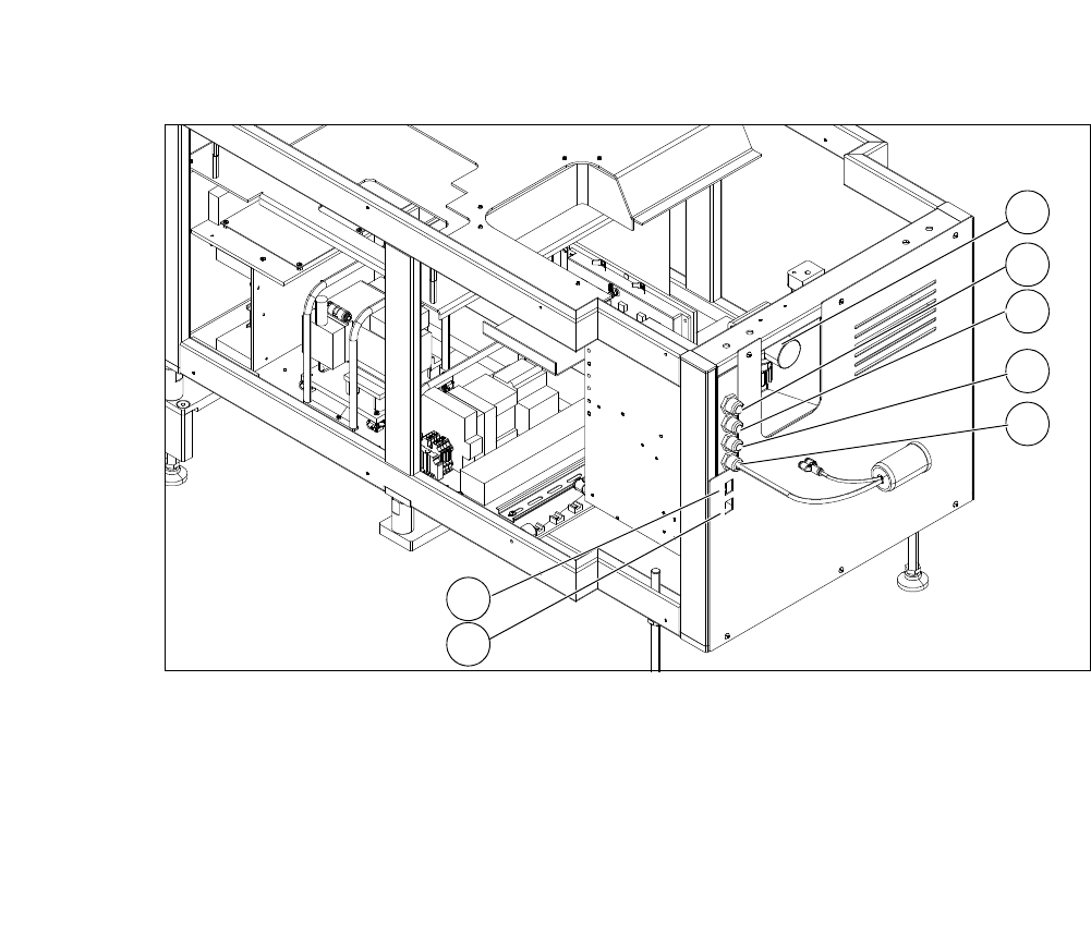
3.7.6.1 Supply Unit
Fig. 3.7 - 15 Supply unit
3
(1) Manometer for compressed air supply (2) Voltage supply
(3) Communication with SIPLACE machine (4) CAN bus
(5) Compressed air connection (modified
adapter dummy connector [03011592-01])
(6) LAN1
(7) LAN2
2
1
3
4
5
6
7
3 Technical Data User Manual SIPLACE CA
3.7 SIPLACE Wafer System (SWS) Edition 08/2011 EN
164
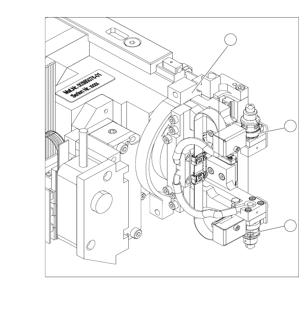
3.7.6.2 Flip Unit
3
Fig. 3.7 - 16 Flip unit
3
3
(1) Flip head (2) Nozzle or tool take-up
1
2
2
User Manual SIPLACE CA 3 Technical Data
Edition 08/2011 EN 3.7 SIPLACE Wafer System (SWS)
165
3
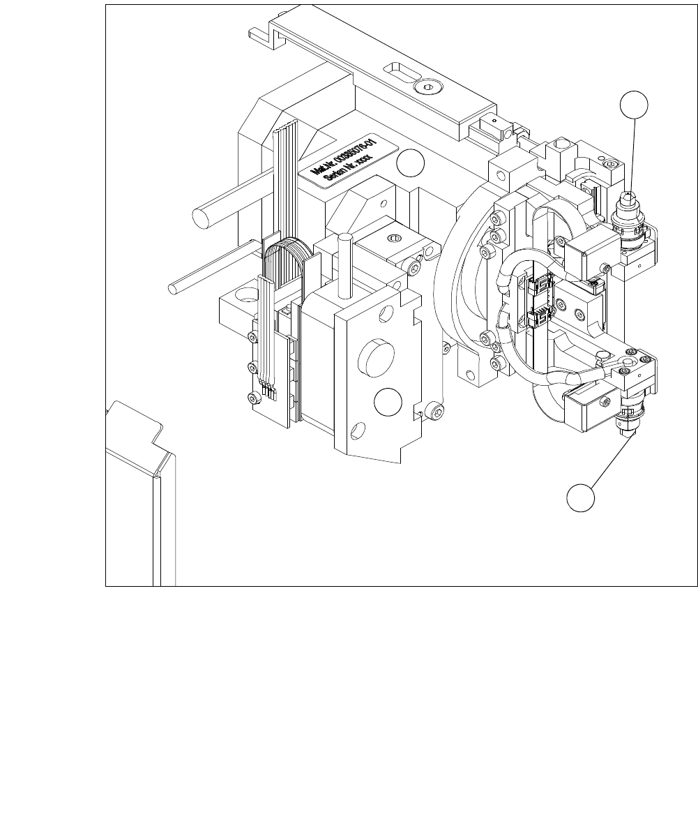
Fig. 3.7 - 17 Flip head - front view
(1) Nozzle take up, segment 1
(2) Nozzle take up, segment 2
(3) Motor for linear movement
(4) Motor for 180° rotation
The flip unit takes the ejected die from the wafer foil. In flip chip mode, it rotates the die by 180°
into the pickup position for the placement head. In die attach mode the flip unit rotates the die by
approx. 130° into the handover position to the die attach unit.
The flip unit is equipped with two nozzles that are arranged in opposite positions by 180°. This
enables the system in flip chip mode to pick up a new die from the wafer at the same time as the
placement head performs pickup.
1
3
4
2