00195941-03-UM SiplaceCA-EN.pdf - 第171页
User Manual SIPLACE CA 3 Technical Data Edition 08/2011 EN 3.7 SIPLACE Wafer System (SWS) 171 Fig. 3.7 - 22 Die ejector base unit (1) Z axis (2) Z-axis movement (pneu matic) 1 2
3 Technical Data User Manual SIPLACE CA
3.7 SIPLACE Wafer System (SWS) Edition 08/2011 EN
170
3.7.6.5 Die Ejector
According to the location (2 and 4 or 1 and 3) there are two different variants that only differ in their
mirror-inverted arrangement of the modules.
3
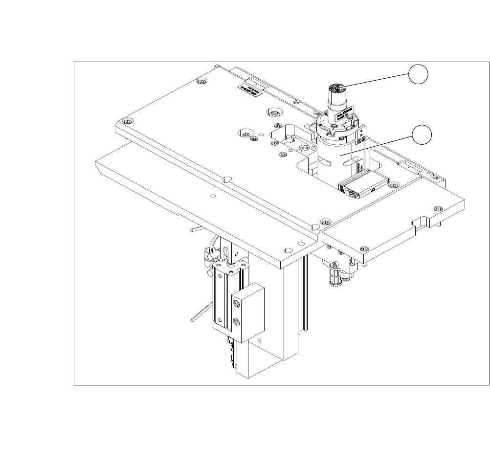
Fig. 3.7 - 21 Main modules of the die ejector
(1) Ejector tool
(2) Z axis
1
2
User Manual SIPLACE CA 3 Technical Data
Edition 08/2011 EN 3.7 SIPLACE Wafer System (SWS)
171
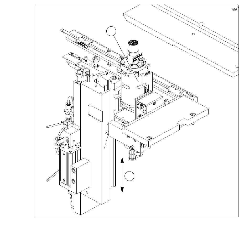
Fig. 3.7 - 22 Die ejector base unit
(1) Z axis
(2) Z-axis movement (pneumatic)
1
2
3 Technical Data User Manual SIPLACE CA
3.7 SIPLACE Wafer System (SWS) Edition 08/2011 EN
172
3.7.6.6 Ejection Tool
3
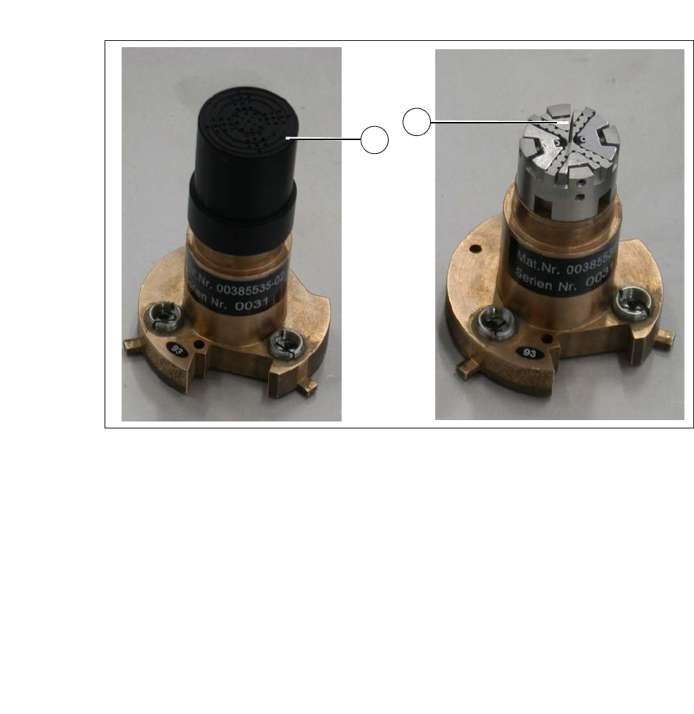
Fig. 3.7 - 23 Ejection tool
(1) Vacuum cap
(2) Ejection needle
The die ejector is needed to separate the die from the wafer foil. It consists of a base unit and the
ejection tool.
The ejection tool is mounted to the base unit and consists of the interface, the needle system and
a vacuum cap.
The wafer foil is sucked up to the vacuum cap by a vacuum, the needle system travels upwards
and removes the die from the wafer foil. Now the die can be picked up by the nozzle of the flip unit.
The ejector tool needs to be adjusted to the size of the die and can therefore be exchanged to suit
requirements. It is fixed to the base unit by means of a bayonet lock.
The ejector tool can be equipped with 2 different needle types:
– Non-piercing needles
These cause the wafer foil to arch and therefore release the die. The wafer foil is not pierced
in this case, so that the components are not touched by the needles.
– Piercing needles
These pierce the wafer foil and lift the die directly off the foil.
1
2