00195941-03-UM SiplaceCA-EN.pdf - 第185页
User Manual SIPLACE CA 3 Technical Data Edition 08/2011 EN 3.8 Placement Heads 185 3.8.3 20 Segment Coll ect&Place CA Head 3 Fig. 3.8 - 3 20 segment Collect&Place CA head - function groups part 1 (1) DP drive, 20…
3 Technical Data User Manual SIPLACE CA
3.8 Placement Heads Edition 08/2011 EN
184
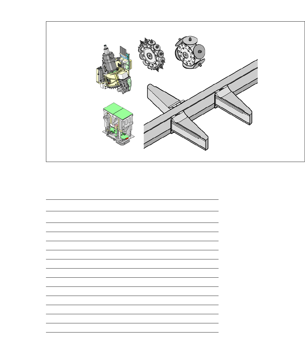
3.8.2 Placement Head Configurations for CA3 Placement Machines
3
3
Fig. 3.8 - 2 Placement head configuration - SIPLACE CA3
Possible placement head configurations 3
3
Placement area 2
Placement area 1
TH
C&P12CA
G1
G3
G4
C&P20CA/C&P12CA/
C&P6CA/TH
C&P20CA/C&P12CA/
C&P6CA/TH
C&P20CA/C&P12CA/
C&P6CA/TH
C&P6CA
C&P20CA
Placement area 1 Placement area 2
Gantry 1 Gantry 4 Gantry 3
C&P20CA C&P20CA C&P12
C&P20CA C&P20CA C&P6
C&P20CA C&P20CA TH
a
a) A TwinHead can only be used in a placement area without SWS.
C&P12 C&P12 C&P12
C&P12 C&P12 C&P6
C&P12 C&P12 TH
C&P12 C&P6 C&P12
C&P12 C&P6 C&P6
C&P12 C&P6 TH
a
C&P6 C&P6 C&P12
C&P6 C&P6 C&P6
C&P6 C&P6 TH
a
User Manual SIPLACE CA 3 Technical Data
Edition 08/2011 EN 3.8 Placement Heads
185
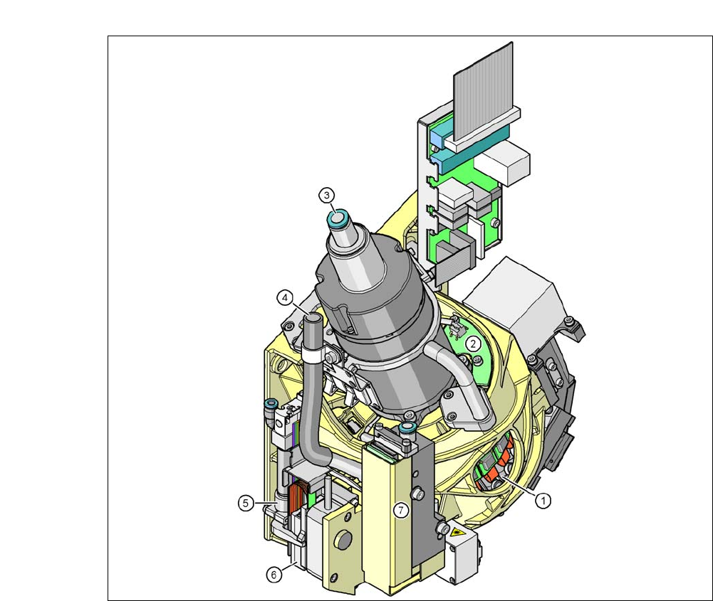
3.8.3 20 Segment Collect&Place CA Head
3
Fig. 3.8 - 3 20 segment Collect&Place CA head - function groups part 1
(1) DP drive, 20 drives
(2) "Vacuum sensor holding circuit"
(3) Compressed air connection for 20 Venturi nozzles of the pick and place holding circuit
(4) Line for the exhaust air from the pressure control valve (7)
(5) Retract cylinder
(6) Z motor (linear motor)
(7) Pressure control valve
3 Technical Data User Manual SIPLACE CA
3.8 Placement Heads Edition 08/2011 EN
186
3
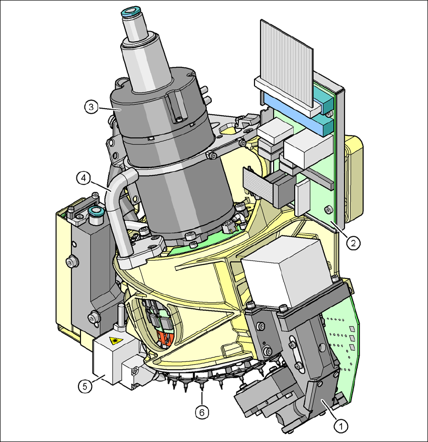
Fig. 3.8 - 4 20 segment Collect&Place CA head - function groups part 2
(1) C&P component camera, type 23, 6 x 6, digital
(2) Intermediate distributor board
(3) Star motor
(4) Handle
(5) Component sensor
(6) Star with 20 nozzles