00195941-03-UM SiplaceCA-EN.pdf - 第189页
User Manual SIPLACE CA 3 Technical Data Edition 08/2011 EN 3.8 Placement Heads 189 3 Fig. 3.8 - 5 Functional Description (1) Component pi ckup position, placement position, r eject position, component check with com- pon…

3 Technical Data User Manual SIPLACE CA
3.8 Placement Heads Edition 08/2011 EN
188
3.8.3.2 Control and Self-Learning Functions
Control and self-learning functions enhance the reliability of the 20 segment Collect&Place CA
head.
– The vertical axis for picking up and placing components is driven by a linear motor. The
travel range is recorded opto-electronically by a linear path measuring system. A sensor
registers the relative movement between the nozzle and the segment when components
are placed and sends a signal to the position control axes. With this sensor stop method,
differences in height during pickup and any unevenness of the board surface are com-
pensated during placement. The average of the deviations during the last 10 placement
operations is taken into account when adapting the further stroke and placement speeds.
The programmed placement force always remains constant.
– To further increase placement reliability, a component sensor has been installed on the
20 segment Collect&Place CA head. At the pickup and placement position, it checks that
the component is present at the nozzle and in addition the component edge ratio. In this
way it is possible to determine whether the component was picked up by the nozzle
transversely or on edge. The beam intensity is also checked regularly to avoid false mea-
surements.
– The package form is also checked and the component is not placed if the geometric data
thus determined differs from the programmed data.
– A digital component camera on the placement head determines the precise position of
each component at the nozzle. The standard camera, type 23 of the 20-Segment Col-
lect&Place-CA heads can optical center modules of the sizes 0,2 mm x 0,2 mm up to 6
mm x 6 mm. Variations of the transfer position are corrected already before placing.
When a component is picked up, the average of the deviations for the last 10 placement
operations is taken into account, thus increasing the pickup accuracy.
3.8.3.3 Functional Description
The 20 segment Collect&Place CA head consists of three axes, the DR or star axis, the Z-axis
and the DP axis.
User Manual SIPLACE CA 3 Technical Data
Edition 08/2011 EN 3.8 Placement Heads
189
3
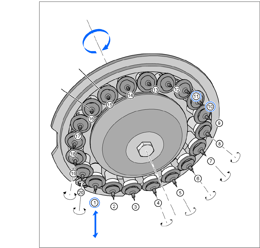
Fig. 3.8 - 5 Functional Description
(1) Component pickup position, placement position, reject position, component check with com-
ponent sensor
(10)Vacuum check of the nozzle in the holding circuit, with or without component
(11) Position for the optical centering of the components
Star rotation
Star axis
DP drive (segment)
Nozzle
Z axis
Check pick up, place or
reject component with com-
ponent sensor
DP axis
Each sleeve can be rotated
individually.
Component
camera for optical
centering
Vacuum- check
of nozzle in hold-
ing circuit

3 Technical Data User Manual SIPLACE CA
3.8 Placement Heads Edition 08/2011 EN
190
Each DP drive, that is in the lowest position of the star (pos. 1 in fig. 3.8 - 5), is raised or lowered
by this axis. thus picking up the components from the feeder modules and setting them down on
the PCB. In order to recognize the set-down height at the placement position a "Z axis down" sen-
sor is used, that recognizes a relative movement between nozzle and segment. When the Z axis
springs into position, this returns a signal - the sensor stop signal - to the axis card that the pre-
control uses to correct the position control. A pneumatic return system was implemented to avoid
the risk of a head crash when the power is switched off due to the segment being lowered with the
sleeve. This keeps the segment securely in the top position when the power is off. Irrespective of
the pneumatic return system (item 5 in fig. 3.8 - 3
), the Z-axis is designed to ensure that in the
event of a power failure, there is sufficient residual power in the servo amplifier to lift the Z-axis
into the top position. A "power fail" signal in the placement machine activates the axis card and
the servo amplifier, so that the Z-axis is moved to the top position.
The Z axis is an "intelligent axis". It "notes" the pickup height of each feeder module track and the
placement height for each component. The placement process can thus be speeded up, while re-
taining the programmed set-down force.
Star axis (item 3 in fig. 3.8 - 4) 3
The star rotates about the star axis with its 20 DP drives. This is tilted away from the vertical. A
three-phase servomotor with position control is used as the drive motor. An opto-electronic en-
coder returns information about the angle of rotation at the axis card. The actual position values
are analyzed on the axis card. The position control on the axis card provides the nominal current
and voltage values for the servo amplifier used to operate the star motor. On each DP drive there
is a nozzle that sucks up the component during the pickup process. The star transports the com-
ponent picked up from the pick/place position (item 1 in fig. 3.8 - 5
) to the optical centering position
(item 11 in fig. 3.8 - 5
) and then on to the pick/place position for placement. On the way to the
pickup/placement position, the DP drive rotates the component into the required placement posi-
tion.
Z-axis (item 6 in fig. 3.8 - 3) 3
The Z axis performs a vertical movement. A three-phase linear motor is used as the drive. An
opto-electronic encoder is used to measure positions. A scanner scans the positioning fiducials
on a tape measure and thus returns the position signals to the axis card.
The Z motor is operated with position control. The actual position values are analyzed on the axis
card. The position control on the axis card provides the nominal current and voltage values for the
servo amplifier used to operate the star motor.