00195941-03-UM SiplaceCA-EN.pdf - 第194页
3 Technical Data User Manual SIPLACE CA 3.8 Placement Heads Edition 08/2011 EN 194 3.8.4 12 Segment Collect & Place CA Head 3 Fig. 3.8 - 6 12 segment Collect&Place CA head - function grou ps part 1 3 (1) V acuum …

User Manual SIPLACE CA 3 Technical Data
Edition 08/2011 EN 3.8 Placement Heads
193
3.8.3.4 Technical Data
3
3.8.3.5 Component Reject Bin Sensor
NOTE 3
We recommend to install the optional component sensor for the component reject bin at a loca-
tion without SWS when a 20 segment Collect&Place head is used. (See section 7.2, page 461)
Range of components
a
a) Please note that the component range that can be placed is also affected by the pad geometry, the customer-spe-
cific standards and the packaging tolerances.
01005 to 2220, Melf, SOT, SOD
Component specifications
Maximum height
Min. lead pitch
Min. lead width
Min. ball pitch
Min. ball diameter
Min. dimensions
Maximum dimensions
Max. weight
4 mm
80 µm
30 µm
100 µm
50 µm
0.12 mm x 0.12 mm
6 mm x 6 mm
1 g
Nozzle types 10xx, 11xx, 12xx
X/Y accuracy (SMD) ± 41 µm/3 , ± 55 µm/4
X/Y accuracy (CA) ± 25 µm/3, ± 33 µm/4
Angular accuracy ± 0.5°/3± 0.7°/4
3 Technical Data User Manual SIPLACE CA
3.8 Placement Heads Edition 08/2011 EN
194
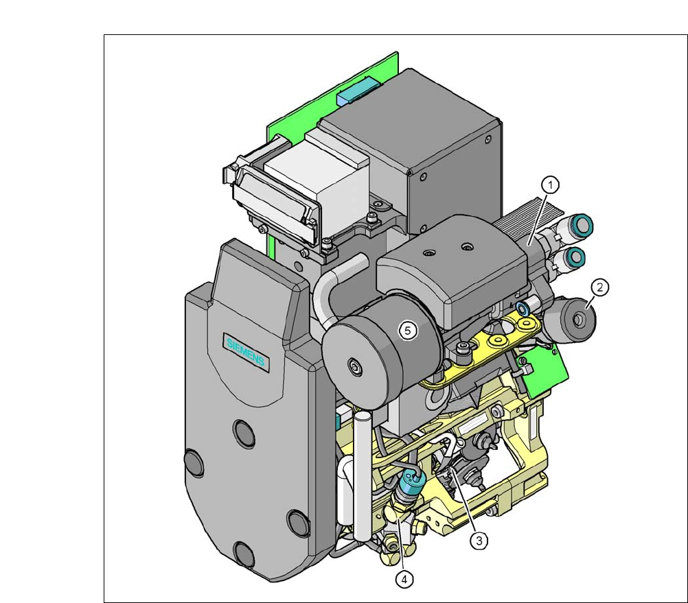
3.8.4 12 Segment Collect & Place CA Head
3
Fig. 3.8 - 6 12 segment Collect&Place CA head - function groups part 1
3
(1) Vacuum generator
(2) Turning station, DP axis
(3) Star with 12 sleeves, star axis
(4) Air kiss valve
(5) Silencer
User Manual SIPLACE CA 3 Technical Data
Edition 08/2011 EN 3.8 Placement Heads
195
3
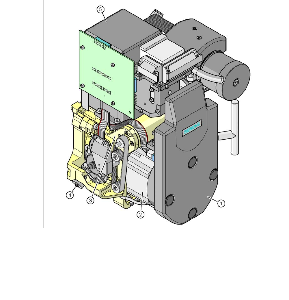
Fig. 3.8 - 7 12 segment Collect&Place CA head - function groups part 2
3
(1) Intermediate distributor board (beneath the cover)
(2) Star drive - DR motor
(3) Z axis motor
(4) Valve positioning drive
(5) Component camera C&P, type 29, (27 x 27) digital, high-resolution
3.8.4.1 Description
The 12 segment Collect&Place CA head functions according to the Collect&Place principle i.e.
twelve components are picked up from the placement head during each cycle, are optically cen-
tered on the way to the placement position and are then rotated into the required placement posi-
tion. They are then set down gently and accurately on the PCB with a blast of air.