00195941-03-UM SiplaceCA-EN.pdf - 第195页
User Manual SIPLACE CA 3 Technical Data Edition 08/2011 EN 3.8 Placement Heads 195 3 Fig. 3.8 - 7 12 segment Collect&Place CA head - function groups part 2 3 (1) Intermedia te distributor board (beneath the cover) (2…
3 Technical Data User Manual SIPLACE CA
3.8 Placement Heads Edition 08/2011 EN
194
3.8.4 12 Segment Collect & Place CA Head
3
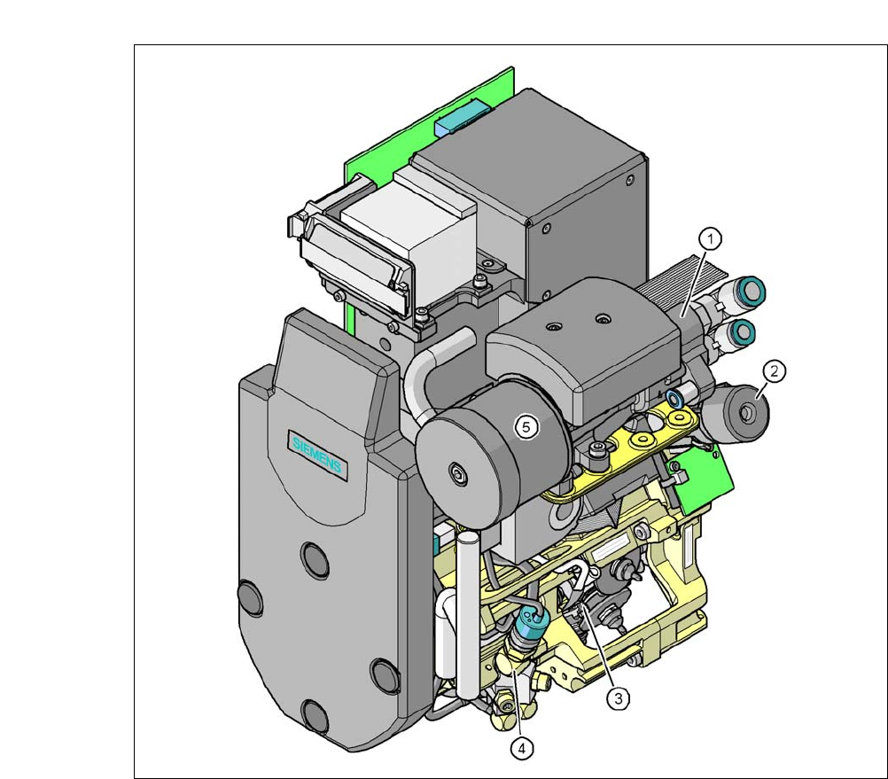
Fig. 3.8 - 6 12 segment Collect&Place CA head - function groups part 1
3
(1) Vacuum generator
(2) Turning station, DP axis
(3) Star with 12 sleeves, star axis
(4) Air kiss valve
(5) Silencer
User Manual SIPLACE CA 3 Technical Data
Edition 08/2011 EN 3.8 Placement Heads
195
3
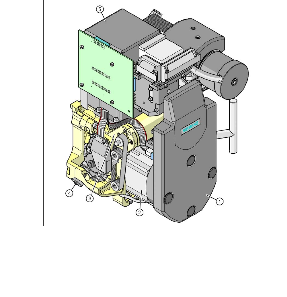
Fig. 3.8 - 7 12 segment Collect&Place CA head - function groups part 2
3
(1) Intermediate distributor board (beneath the cover)
(2) Star drive - DR motor
(3) Z axis motor
(4) Valve positioning drive
(5) Component camera C&P, type 29, (27 x 27) digital, high-resolution
3.8.4.1 Description
The 12 segment Collect&Place CA head functions according to the Collect&Place principle i.e.
twelve components are picked up from the placement head during each cycle, are optically cen-
tered on the way to the placement position and are then rotated into the required placement posi-
tion. They are then set down gently and accurately on the PCB with a blast of air.

3 Technical Data User Manual SIPLACE CA
3.8 Placement Heads Edition 08/2011 EN
196
In contrast to conventional chip shooters, the twelve nozzles on the SIPLACE Collect&Place CA
heads rotate around a horizontal axis. This not only saves space: the shorter diameter reduces
the centrifugal forces significantly. This means that the danger of component slip during the trans-
port is largely ruled out.
An additional benefit: the Collect&Place CA head cycle times are the same for all components,
which means that the placement rate is not dependent on the component size.
3.8.4.2 Control and Self-Learning Functions
Control and self-learning functions enhance the reliability of the 12 segment Collect&Place CA
head.
– The vertical axis (Z axis) for picking up and placing the component works in sensor stop
mode, in which differences in height during pickup and any unevenness of the PCB surface
are compensated during placement. The average of the deviations during the last 10 place-
ment operations is also taken into account when adapting the further stroke and placement
speeds. The programmed placement force always remains constant.
– Vacuum checks at the nozzles indicate whether the component was picked up or set down
correctly.
– To further increase placement reliability, a component sensor can be installed on the C&PCA
head. The component sensor checks the edge ratio of the components, in addition to whether
the component is present at the nozzle. In this way it is possible to determine whether the
component was picked up by the nozzle transversely or on edge.
– The package form is also checked, and the component is not placed if the geometric data thus
determined differs from the programmed data.
– A digital component camera on the placement head determines the precise position of each
component at the nozzle. With the standard camera modules of the size 0,5 mm x 0,5 mm up
to 18,7 mm x 18,7 mm can beoptical centered. Variations of the transfer position are cor-
rected already before placing. When a component is picked up, the average of the deviations
for the last 10 placement operations is taken into account. This further increases the pickup
accuracy.
– With the help of an optional, high resolution C&P component camera the 12 segment-
Collect&Place-CA-head can optically center and place modules of the size 0,4 mm x 0,2 mm
up to 18,7 mm x 18,7 mm . When placing high speed, flip chip and bare die -components, this
high-resolution digital camera optimizes both the speed and the accuracy. The values can be
found in the table on page 198
.
3.8.4.3 Functional Description
The 12 segment Collect&Place CA head consists of three axes, the DR or star axis, the Z-axis
and the DP axis.