00195941-03-UM SiplaceCA-EN.pdf - 第198页
3 Technical Data User Manual SIPLACE CA 3.8 Placement Heads Edition 08/2011 EN 198 3.8.4.4 T echnical Dat a 3 12 segment Collect&Place CA head with high-resolution component camera, type 29, 27 x 27, digital (see sec…
User Manual SIPLACE CA 3 Technical Data
Edition 08/2011 EN 3.8 Placement Heads
197
3
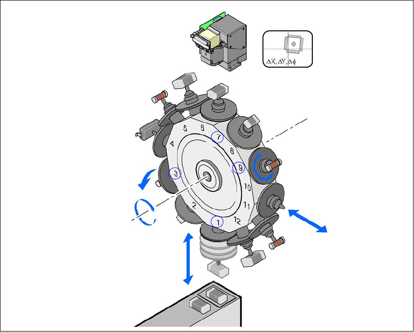
Fig. 3.8 - 8 Functional description
The star rotates about the star axis with its 12 segments. The segments hold the sleeves. There
is a nozzle seated on every sleeve, which sucks up the components, and transports them from
the pickup/placement position (1) to the reject position (3), to the optical centering position (7) or
to the turning position (9).
The Z axis performs a vertical movement. Every sleeve that is in the bottom star position (1) is
raised or lowered by this axis, thus picking up the components from the feeder modules and set-
ting them down on the PCB. The Z axis is an "intelligent axis". It "notes" the pickup height of each
feeder module track and the placement height for each component. This can speed up the place-
ment process. The programmed placement force remains constant.
The DP axis rotates the optically centered component to the desired placement angle.
The sequences of movements of the rotation and translation axes are controlled by control cir-
cuits. Position and speed sensors send the actual values for the axis movement to the axis control.
The nominal and actual values are compared and used to determine the force and speed param-
eters for the servo amplifier, and thus the axis movement to be performed. -The vacuum values
at the nozzle are constantly checked throughout the entire pickup and placement process in order
to keep the placement error rate as low as possible.
Component camera
DP axis
Rotate component
into placement position
Remove or insert sleeve
Z axis
Pick up component
or place it
Star axis
Star rotation
Reject component
3 Technical Data User Manual SIPLACE CA
3.8 Placement Heads Edition 08/2011 EN
198
3.8.4.4 Technical Data
3
12 segment Collect&Place CA head with high-resolution
component camera, type 29, 27 x 27, digital
(see section
7.12, page 478)
Range of components
a
a) Please note that the component range that can be placed is also affected by the pad geometry, the customer-spe-
cific standards and the packaging tolerances.
0201
b
to flip chip, bare die, PLCC44, BGA, µBGA, TSOP,
QFP, SO to SO32, DRAM
b) With 0201 package
Component specifications
Maximum height
Min. lead pitch
Min. lead width
Min. ball pitch
Min. ball diameter
Min. dimensions
Maximum dimensions
Max. weight
6 mm
0.3 mm
0.15 mm
0.13 mm
0.08 mm
0,6 mm x 0,3 mm
18,7 mm x 18,7 mm
2 g
Nozzle types 9 xx
X/Y accuracy (SMD) ± 41 µm/3± 55 µm/4
X/Y accuracy (CA) ± 25 µm/3, ± 33 µm/4
Angular accuracy ± 0.5°/3, ± 0.7°/4
User Manual SIPLACE CA 3 Technical Data
Edition 08/2011 EN 3.8 Placement Heads
199
3.8.5 6 Segment Collect&Place CA Head
3
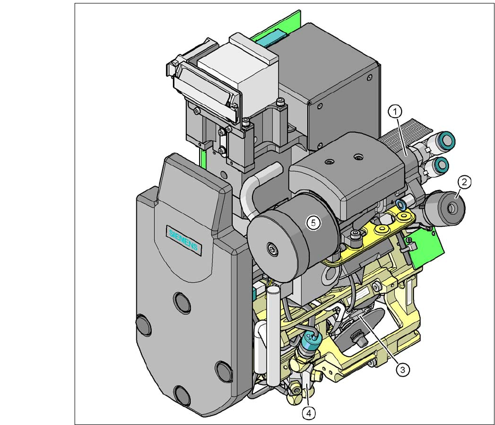
Fig. 3.8 - 9 6 segment Collect&Place CA head - function groups part 1
(1) Vacuum generator
(2) Turning station, DP axis
(3) Star with 6 sleeves, star axis
(4) Air kiss valve
(5) Silencer