00195941-03-UM SiplaceCA-EN.pdf - 第199页
User Manual SIPLACE CA 3 Technical Data Edition 08/2011 EN 3.8 Placement Heads 199 3.8.5 6 Segment Co llect&Place CA Head 3 Fig. 3.8 - 9 6 segment Collect&Place CA head - function groups part 1 (1) V acuum genera…
3 Technical Data User Manual SIPLACE CA
3.8 Placement Heads Edition 08/2011 EN
198
3.8.4.4 Technical Data
3
12 segment Collect&Place CA head with high-resolution
component camera, type 29, 27 x 27, digital
(see section
7.12, page 478)
Range of components
a
a) Please note that the component range that can be placed is also affected by the pad geometry, the customer-spe-
cific standards and the packaging tolerances.
0201
b
to flip chip, bare die, PLCC44, BGA, µBGA, TSOP,
QFP, SO to SO32, DRAM
b) With 0201 package
Component specifications
Maximum height
Min. lead pitch
Min. lead width
Min. ball pitch
Min. ball diameter
Min. dimensions
Maximum dimensions
Max. weight
6 mm
0.3 mm
0.15 mm
0.13 mm
0.08 mm
0,6 mm x 0,3 mm
18,7 mm x 18,7 mm
2 g
Nozzle types 9 xx
X/Y accuracy (SMD) ± 41 µm/3± 55 µm/4
X/Y accuracy (CA) ± 25 µm/3, ± 33 µm/4
Angular accuracy ± 0.5°/3, ± 0.7°/4
User Manual SIPLACE CA 3 Technical Data
Edition 08/2011 EN 3.8 Placement Heads
199
3.8.5 6 Segment Collect&Place CA Head
3
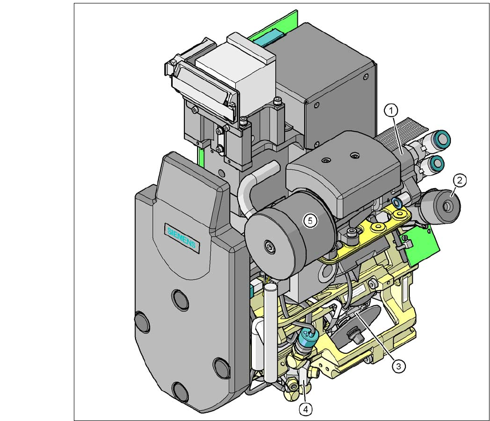
Fig. 3.8 - 9 6 segment Collect&Place CA head - function groups part 1
(1) Vacuum generator
(2) Turning station, DP axis
(3) Star with 6 sleeves, star axis
(4) Air kiss valve
(5) Silencer
3 Technical Data User Manual SIPLACE CA
3.8 Placement Heads Edition 08/2011 EN
200
3
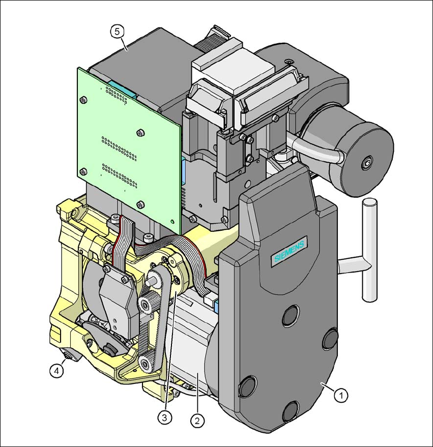
Fig. 3.8 - 10 6 segment Collect&Place CA head - function groups part 2
3
(1) Intermediate distributor board, beneath the cover
(2) Star drive - DR motor
(3) Z axis motor
(4) Valve positioning drive
(5) C&P component camera, type 29, 27 x 27, digital