00195941-03-UM SiplaceCA-EN.pdf - 第201页
User Manual SIPLACE CA 3 Technical Data Edition 08/2011 EN 3.8 Placement Heads 201 3.8.5.1 Description The 6 segment Collect&Place CA head a lso functi ons according to the Collect&Place principle. With the high-…
3 Technical Data User Manual SIPLACE CA
3.8 Placement Heads Edition 08/2011 EN
200
3
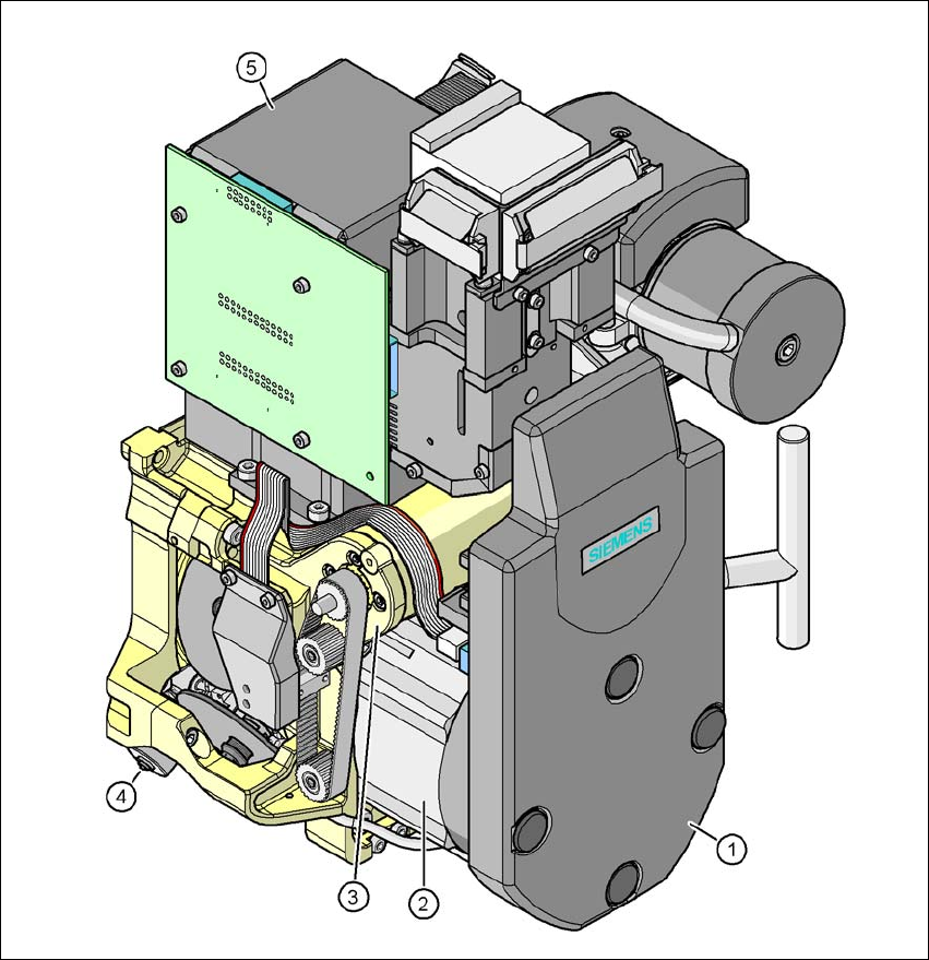
Fig. 3.8 - 10 6 segment Collect&Place CA head - function groups part 2
3
(1) Intermediate distributor board, beneath the cover
(2) Star drive - DR motor
(3) Z axis motor
(4) Valve positioning drive
(5) C&P component camera, type 29, 27 x 27, digital
User Manual SIPLACE CA 3 Technical Data
Edition 08/2011 EN 3.8 Placement Heads
201
3.8.5.1 Description
The 6 segment Collect&Place CA head also functions according to the Collect&Place principle.
With the high-resolution digital component camera, the 6 segment Collect&Place CA head accu-
rately and rapidly places components with an edge length of up to 27 mm. It is therefore ideal for
use with products containing a large proportion of ICs. A considerable increase in output can be
achieved even in the main application range from PLCC 44 to QFP 208.
3.8.5.2 Control and Self-Learning Functions
The control and self-learning functions described on page 196 for the 12 segment Collect&Place
CA head also apply to the 6 segment Collect&Place CA head.
3.8.5.3 Functional Description
3
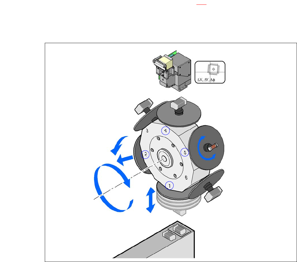
Fig. 3.8 - 11 Functional Description
The 6 segment Collect&Place CA head consists of three axes, the DR or star axis, the Z-axis
and the DP axis.
Component camera
DP axis
Rotate component
into placement position
Remove or insert sleeve
Z axis
Pick up component
or place it
Star axis
Star rotation
Reject component
3 Technical Data User Manual SIPLACE CA
3.8 Placement Heads Edition 08/2011 EN
202
The star rotates about the star axis with its 6 segments. The segments hold the sleeves.
There is a nozzle seated on every sleeve, which sucks up the components, and transports
them from the pickup/placement position (1) to the reject position (2), to the optical centering
position (4) or to the turning position (5).
The Z axis performs a vertical movement. Every sleeve that is in the bottom star position (1)
is raised or lowered by this axis, thus picking up the components from the feeder modules
and setting them down on the PCB. The Z axis is an "intelligent axis". It "notes" the pickup
height of each feeder module track and the placement height for each component. This can
speed up the placement process. The programmed placement force remains constant.
The DP axis rotates the optically centered component to the desired placement angle. The
sequences of movements of the rotation and translation axes are controlled by control cir-
cuits. Position and speed sensors send the actual values for the axis movement to the axis
control. The nominal and actual values are compared and used to determine the force and
speed parameters for the servo amplifier, and thus the axis movement to be performed. The
vacuum values at the nozzle are constantly checked throughout the entire pickup and place-
ment process in order to keep the placement error rate as low as possible.