00195941-03-UM SiplaceCA-EN.pdf - 第207页
User Manual SIPLACE CA 3 Technical Data Edition 08/2011 EN 3.8 Placement Heads 207 3.8.6.3 T echnical Dat a Optical cent ering with Restriction: The SWS cannot be comb ined with a T winHead. S tationary P&P component…
3 Technical Data User Manual SIPLACE CA
3.8 Placement Heads Edition 08/2011 EN
206
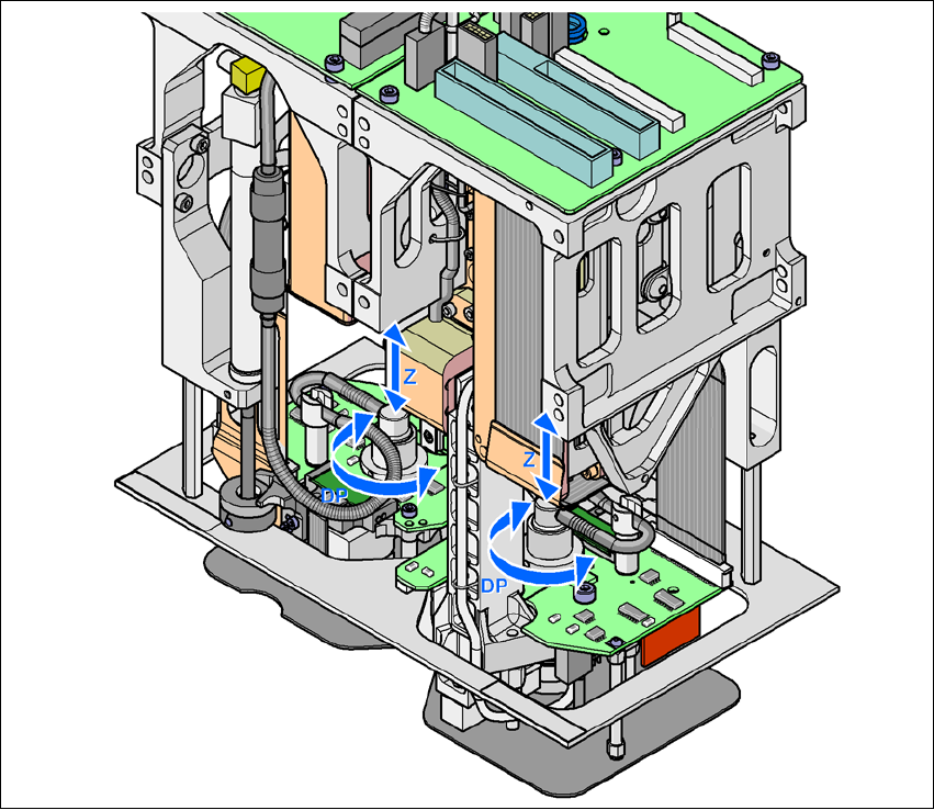
The sequences of movements of the rotation and translation axes are controlled by control cir-
cuits. Position and speed sensors send the actual values for the axis movement to the axis control.
The nominal and actual values are compared and used to determine the force and speed param-
eters for the servo amplifier, and thus the axis movement to be performed.
The vacuum values at the nozzle are constantly checked throughout the entire pickup and place-
ment process in order to keep the placement error rate as low as possible.
3
Fig. 3.8 - 13 Functional Description
User Manual SIPLACE CA 3 Technical Data
Edition 08/2011 EN 3.8 Placement Heads
207
3.8.6.3 Technical Data
Optical centering with
Restriction:
The SWS cannot be combined
with a TwinHead.
Stationary P&P component camera
(type 33) 55 x 45, digital
(see Section 3.13.5, page 229)
Stationary P&P component camera
(type 25) 16 x 16, digital
(see Section 7.4, page 463)
Range of components
a
a) Please note that the component range that can be placed is also affected by the pad geometry, the customer-spe-
cific standards and the packaging tolerances.
0402 to SO, PLCC, QFP, BGA, spe-
cial component, bare die, flip chip
0201 to SO, PLCC, QFP, sockets,
plugs, BGA, special components,
bare dies, flip-chips, shields
Component specifications
Maximum height
Min. lead pitch
Min. lead width
Min. ball pitch
min. ball diameter
Min. dimensions
Maximum dimensions
Max. weight
25 mm (higher heights on request)
0.3 mm
0.15 mm
0.35 mm
0.2 mm
1,0 mm x 0,5 mm
55 45 mm (simple measurement)
For use with two nozzles
50 mm x 50 mm or
69 mm x 10 mm
When operating with a nozzle:
85 mm x 85 mm or
125 mm x 10 mm
Max. 200 mm x 125 mm (with
restrictions)
100 g
b
b) If standard nozzles are used
25 mm (higher heights on request)
0.25 mm
0.1 mm
0.14 mm
0.08 mm
1,0 mm x 0,5 mm
16 mm (simple measurement)
100 g
b
Programmable set-down force 1.0 N - 15 N
2.0 N - 30 N
c
c) SIPLACE high-force head, section 7.3, page 462.
1.0 N - 15 N
2.0 N - 30 N
c
Nozzle types 5 xx (standard)
4 xx + adapter
8 xx + adapter
9 xx + adapter
5 xx (standard)
4 xx + adapter
8 xx + adapter
9 xx + adapter
Nozzle distance of the two
Pick&Place heads
70.8 mm 70.8 mm
X/Y accuracy (SMD) ± 26 µm/3, ± 35 µm/4 ± 22 µm / 3 , ± 30 µm / 4
Angular accuracy ± 0.05° / 3, ± 0.07° / 4 ± 0.05° / 3, ± 0.07° / 4
3 Technical Data User Manual SIPLACE CA
3.9 Electrical and Pneumatic Connection Points Edition 08/2011 EN
208
3.9 Electrical and Pneumatic Connection Points
3.9.1 Electrical Connection Points (Placement Machine)
3
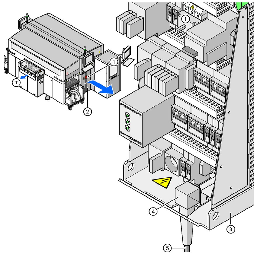
Fig. 3.9 - 1 Electrical connection point on the placement machine
(1) Main switch
(2) Cover above the power supply unit
(3) Power supply unit
(4) Angled cable gland
(5) Power cable
(T) Direction of PCB transport