00195941-03-UM SiplaceCA-EN.pdf - 第22页
1 Introduction User Manual SIPLACE CA 1.1 Machine D escription Edition 08/2011 EN 22 1 Fig. 1.1 - 1 Placement principle acco rding to the Collect &Place procedure 1.1.2 Extensions The following options can be used to…

User Manual SIPLACE CA 1 Introduction
Edition 08/2011 EN 1.1 Machine Description
21
1.1.1 The SIPLACE Principle
The SIPLACE Wafer Systems make bare dies available in fixed pickup positions, for pickup with
the die attach or flip chip methods. The other components are made available by the fixed feeders
on the component trolley and on the trays of the Matrix Tray Changer. The placement heads pick
the bare dies and components up and place these on the waiting printed circuit boards.
The placement machines in the CA series have two placement areas:
– As in the case of SIPLACE X machines, up to two boards can be processed simultaneously
for single conveyors and up to four boards can be processed at the same time for dual con-
veyors.
The principle of the "stationary component supply" and "stationary PCB", which has proved highly
suitable for all SIPLACE placement machines, has a number of significant advantages:
– The refilling of components or splicing on of new tapes does not cause machine standstill.
– The vibration-free feeding in of components enables reliable pickup of even the smallest com-
ponents (e.g. 01005) and bare dies.
– The PCB, which does not move during the placement process, prevents the components slip-
ping.
– The combination of placement heads with nozzle changers always guarantees an optimum
nozzle configuration for every placement process, thus minimizing traversing paths and opti-
mizing the placement sequence.
High flexibility, economic efficiency and reliable setups are the guarantee for the high level of pro-
ductivity in the SIPLACE CA series. Minimum down times increase utilization and thus help to in-
crease productivity.
Since this new concept combines at least two production lines to form a single line (SMD and bare
die placement), the investment costs and cost of ownership can be reduced significantly.
1 Introduction User Manual SIPLACE CA
1.1 Machine Description Edition 08/2011 EN
22
1
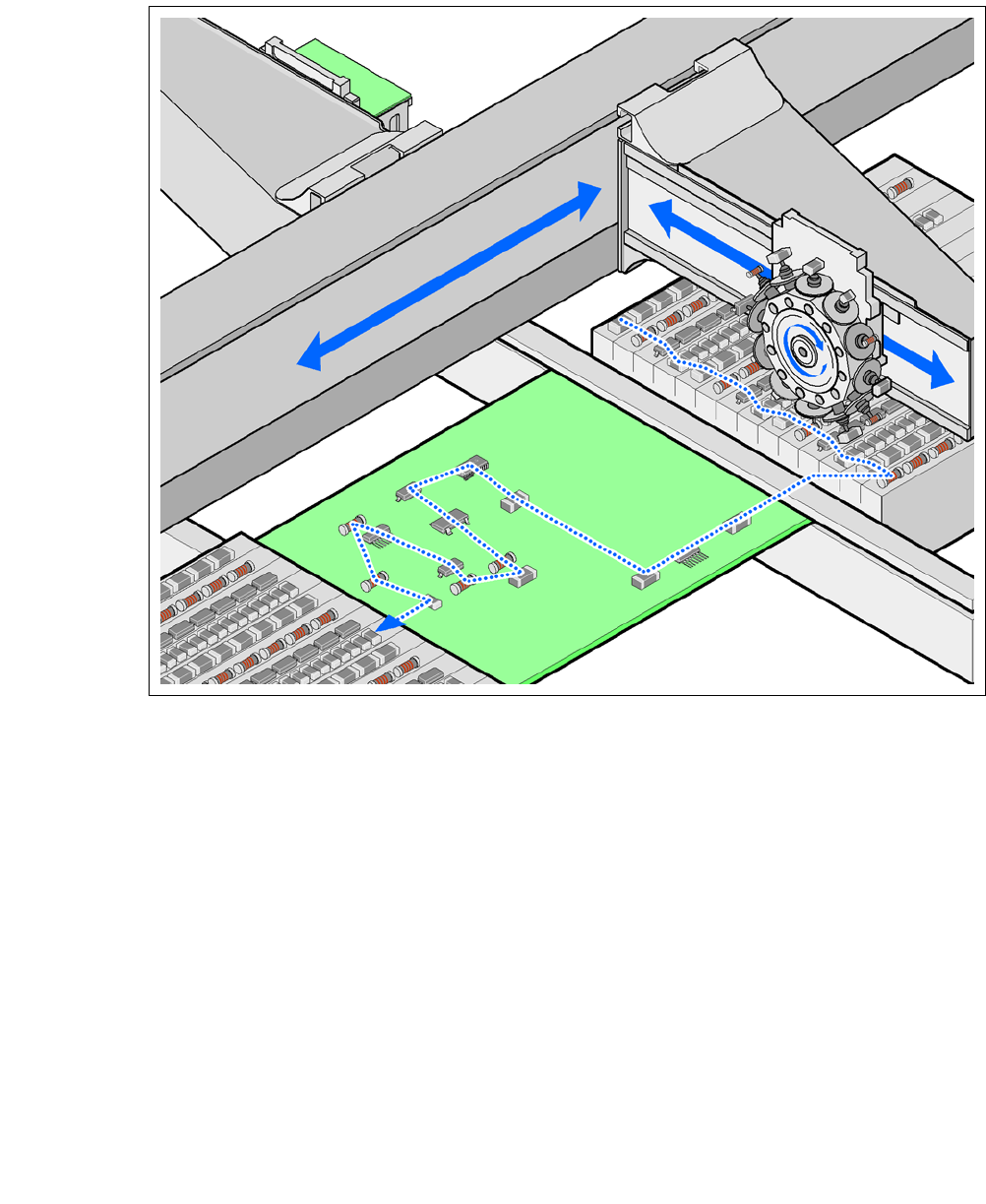
Fig. 1.1 - 1 Placement principle according to the Collect &Place procedure
1.1.2 Extensions
The following options can be used to extend the range of functions supported by the placement
machines:
– Additional component trolleys increase the placement machine utilization, since external pre-
setup configurations reduce the setup times.
– The dual conveyor also increases machine utilization by eliminating nonproductive PCB
transport times.
– Automatic nozzle changers speed up and optimize the nozzle configuration process.
– PCB barcode scanners allow the production setup to be changed over when triggered by a
new product.
– Large and sensitive components can be supplied in trays in add-on matrix tray changers.
– The productivity lift implements the concept of parallel placement. Furthermore the relation
between productive and non productive times can be improved with it.

User Manual SIPLACE CA 1 Introduction
Edition 08/2011 EN 1.1 Machine Description
23
1.1.3 SIPLACE CA4
The CA4 placement machine is equipped with four gantries, two for each placement area (PA). All
the gantry axes are driven by linear motors. The gantry axes can be positioned quickly and accu-
rately in the X and Y directions. The gantry arms are lightweight constructions made from a highly
rigid carbon fiber composite material. There is a placement head on each gantry. The following
placement head configurations are possible:
a) Placement area 1 b) Placement area 2 TH only possible with SWS 8
For the performance data refer to section 3.1, page 119.
1.1.4 SIPLACE CA3
The CA3-placement machine has 3 gantries, 2 in the placement area 1 and one in placement area
2. The following placement head configurations are possible:
a) Placement area 1 b) Placement area 2 TH only possible with SWS 8
For the performance data refer to section 3.1, page 119.
1
Placement
heads
Placement heads PA1
a
PA2
b
C&P20CA/
C&P20CA
C&P12CA/
C&P12CA
C&P12CA/
C&P6CA
C&P12CA/
TH
c
C&P6CA/
C&P6CA
C&P6CA/
TH
c
TH/TH
c
C&P20CA/
C&P20CA
yes no no no no no no
C&P12CA/
C&P12CA
yes yes no no no no no
C&P12CA/
C&P6CA
yes yes yes no no no no
C&P6CA/
C&P6CA
yes yes yes no yes no no
C&P12CA/
TH
c
yes yes yes yes no no no
Placement
heads
Placement heads PA1
a
PA2
b
C&P20CA/
C&P20CA
C&P12CA/
C&P12CA
C&P12CA/
C&P6CA
C&P12CA/
TH
c
C&P6CA/
C&P6CA
C&P6CA/
TH
c
TH
C&P20CA yes no no no no no
C&P12CA yes yes no no no no
C&P6CA yes yes yes no yes no
TH
c
yes yes yes yes yes yes