00195941-03-UM SiplaceCA-EN.pdf - 第227页
User Manual SIPLACE CA 3 Technical Data Edition 08/2011 EN 3.13 Vision Cameras 227 3.13.3 C&P Component Camera, T ype 41, 6 x 6, Digital Item no.: 03078957-xx 3.13.3.1 Structure 3 Fig. 3.13 - 4 C&P component came…
3 Technical Data User Manual SIPLACE CA
3.13 Vision Cameras Edition 08/2011 EN
226
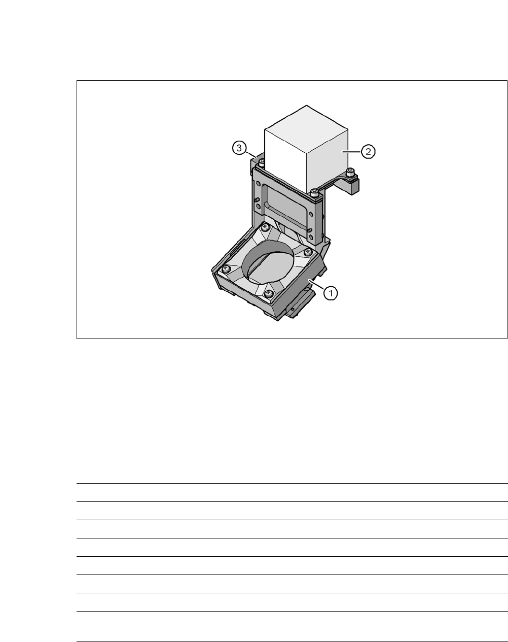
3.13.2 Component Camera C&P, Type 23, 6 x 6, Digital
3.13.2.1 Structure
3
Fig. 3.13 - 3 C&P component camera, type 23, 6 x 6, digital
3
(1) Component camera lens and illumination
(2) Camera amplifier
(3) Illumination control
3.13.2.2 Technical Data
3
Component dimensions 0,18 mm x 0,18 mm to 6 mm x 6 mm
Range of components 01005 to 6 mm x 6 mm
Min. lead pitch 0.25 mm
Min. lead width 0.1 mm
Min. ball pitch 0.13 mm
Min. ball diameter 0.08 mm
Field of vision 8,4 mm x 8,4 mm
Illumination method Front-illumination (5 levels, programable as re-
quired)
User Manual SIPLACE CA 3 Technical Data
Edition 08/2011 EN 3.13 Vision Cameras
227
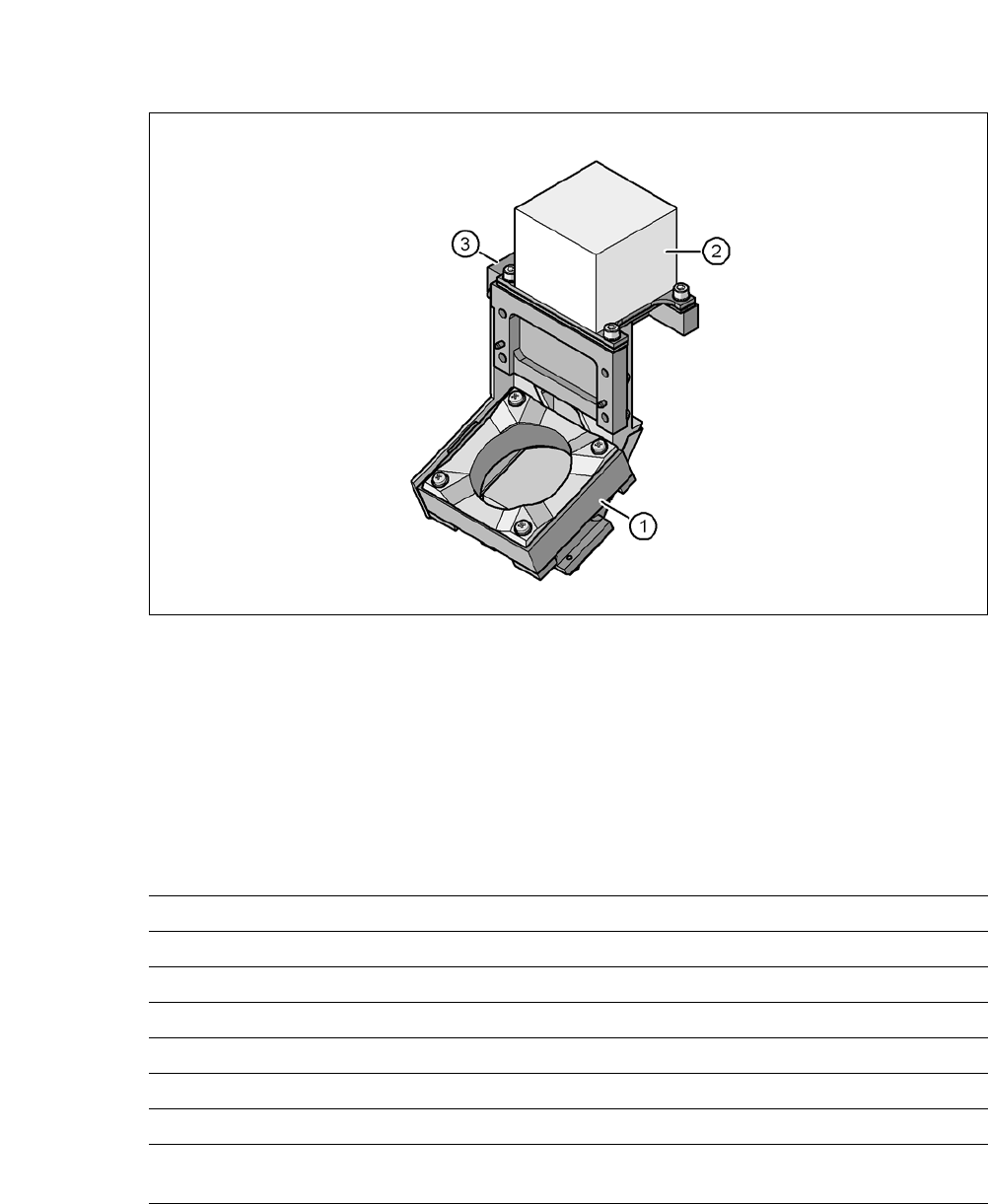
3.13.3 C&P Component Camera, Type 41, 6 x 6, Digital
Item no.: 03078957-xx
3.13.3.1 Structure
3
Fig. 3.13 - 4 C&P component camera, type 41, 6 x 6, digital
3
(1) Component camera lens and illumination
(2) Camera amplifier
(3) Illumination control
3.13.3.2 Technical Data
3
Component dimensions 0.12 mm x 0.12 mm to 6 mm x 6 mm
Range of components Flip Chip (min. thickness 50 µm): 0.8 mm x 0.8 mm
Min. lead pitch 80 µm
Min. lead width 30 µm
Min. ball pitch 100 µm
Min. ball diameter 50 µm
Field of vision 8.9 mm x 8.9 mm
Illumination method Front-illumination (5 levels, programable as re-
quired)
3 Technical Data User Manual SIPLACE CA
3.13 Vision Cameras Edition 08/2011 EN
228
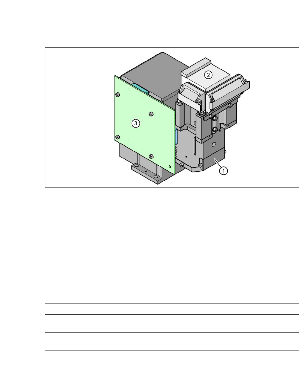
3.13.4 C&P Component Camera, Type 29, 27 x 27, Digital
Standard camera for C&P 12.
3.13.4.1 Structure
3
Fig. 3.13 - 5 C&P component camera, type 29, 27 x 27, digital
(1) Component camera lens and illumination
(2) Camera amplifier
(3) Illumination control
3.13.4.2 Technical Data
3
Component dimensions 0.3 mm x 0.3 mm to 27 mm x 27 mm
Range of components 0201 to 27 mm x 27 mm
PLCC, SO, QFP, TSDP, SOT, MELF, CHIP, IC, BGA
Min. lead pitch 0.3 mm
Min. lead width 0.15 mm
Min. ball pitch 0,13 mm for component < 18 mm x 18 mm;
0,35 mm for component < 18 mm x 18 mm;
Min. ball diameter 0,08 mm for component < 18 mm x 18 mm;
0,2 mm for component < 18 mm x 18 mm;
Field of vision 32 mm x 32 mm
Illumination method Front-illumination (5 levels, programable as required)