00195941-03-UM SiplaceCA-EN.pdf - 第229页
User Manual SIPLACE CA 3 Technical Data Edition 08/2011 EN 3.13 Vision Cameras 229 3.13.5 Component Camera, St ationary , P&P , T ype 33, 55 x 45, Digital 3.13.5.1 Structure 3 Fig. 3.13 - 6 S tructure for the station…
3 Technical Data User Manual SIPLACE CA
3.13 Vision Cameras Edition 08/2011 EN
228
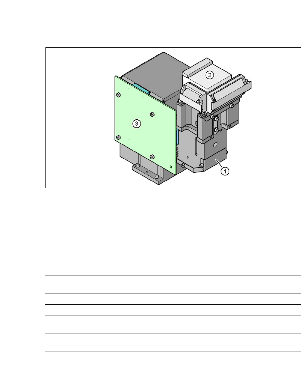
3.13.4 C&P Component Camera, Type 29, 27 x 27, Digital
Standard camera for C&P 12.
3.13.4.1 Structure
3
Fig. 3.13 - 5 C&P component camera, type 29, 27 x 27, digital
(1) Component camera lens and illumination
(2) Camera amplifier
(3) Illumination control
3.13.4.2 Technical Data
3
Component dimensions 0.3 mm x 0.3 mm to 27 mm x 27 mm
Range of components 0201 to 27 mm x 27 mm
PLCC, SO, QFP, TSDP, SOT, MELF, CHIP, IC, BGA
Min. lead pitch 0.3 mm
Min. lead width 0.15 mm
Min. ball pitch 0,13 mm for component < 18 mm x 18 mm;
0,35 mm for component < 18 mm x 18 mm;
Min. ball diameter 0,08 mm for component < 18 mm x 18 mm;
0,2 mm for component < 18 mm x 18 mm;
Field of vision 32 mm x 32 mm
Illumination method Front-illumination (5 levels, programable as required)
User Manual SIPLACE CA 3 Technical Data
Edition 08/2011 EN 3.13 Vision Cameras
229
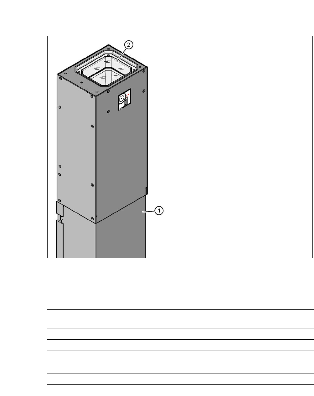
3.13.5 Component Camera, Stationary, P&P, Type 33, 55 x 45, Digital
3.13.5.1 Structure
3
Fig. 3.13 - 6 Structure for the stationary P&P component camera, type 33, 55 x 45, digital
3.13.5.2 Technical Data
3
(1) Camera housing with integral camera
and camera amplifier
(2) Glass plate - illumination and lens below
Component dimensions 0.5 mm x 0.5 mm to 55 mm x 45 mm
Range of components 0402 to SO, PLCC, QFP, BGA, special component, bare die, flip
chip
Min. lead pitch 0.3 mm
Min. lead width 0.15 mm
Min. ball pitch 0.35 mm
Min. ball diameter 0.2 mm
Field of vision 65 mm x 50 mm
Illumination method Front-illumination (6 levels, programable as required)
3 Technical Data User Manual SIPLACE CA
3.13 Vision Cameras Edition 08/2011 EN
230
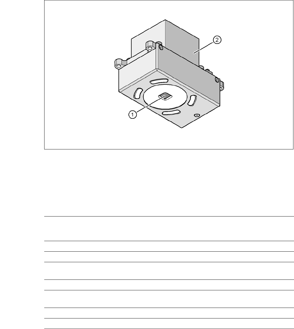
3.13.6 PCB Camera Multicolor, Type 34, Digital
3.13.6.1 Structure
3
Fig. 3.13 - 7 PCB camera multicolor, type 34, digital
(1) PCB camera lens and illumination
(2) Camera amplifier
3.13.6.2 Technical Data
3
PCB fiducials Up to 3 (subpanels and multiple panels)
Up to 6 for the Long board option (Optional PCB fiducials are
output by the optimization.)
Local fiducials Up to 2 per PCB (may be of different type)
Library memory Up to 255 fiducial types per subpanel
Image analysis Edge detection method(singular Feature) on basis of the gray-
scale value
Illumination method Front-illumination (3 levels, programable as required)
Detection time
per fiducial/bad fiducial
20 ms - 200 ms
Field of vision 5,78 mm x 5,78 mm
Distance of focus level 28 mm