00195941-03-UM SiplaceCA-EN.pdf - 第23页
User Manual SIPLACE CA 1 Introduction Edition 08/2011 EN 1.1 Machine Description 23 1.1.3 SIPLACE CA4 The CA4 placement machine is equippe d with four gantries, two for each placement area (P A). All the gantry axes are …
1 Introduction User Manual SIPLACE CA
1.1 Machine Description Edition 08/2011 EN
22
1
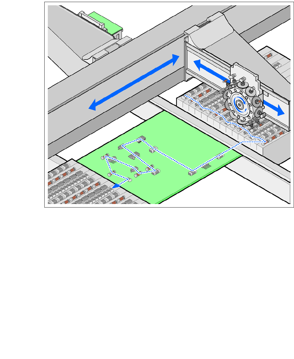
Fig. 1.1 - 1 Placement principle according to the Collect &Place procedure
1.1.2 Extensions
The following options can be used to extend the range of functions supported by the placement
machines:
– Additional component trolleys increase the placement machine utilization, since external pre-
setup configurations reduce the setup times.
– The dual conveyor also increases machine utilization by eliminating nonproductive PCB
transport times.
– Automatic nozzle changers speed up and optimize the nozzle configuration process.
– PCB barcode scanners allow the production setup to be changed over when triggered by a
new product.
– Large and sensitive components can be supplied in trays in add-on matrix tray changers.
– The productivity lift implements the concept of parallel placement. Furthermore the relation
between productive and non productive times can be improved with it.

User Manual SIPLACE CA 1 Introduction
Edition 08/2011 EN 1.1 Machine Description
23
1.1.3 SIPLACE CA4
The CA4 placement machine is equipped with four gantries, two for each placement area (PA). All
the gantry axes are driven by linear motors. The gantry axes can be positioned quickly and accu-
rately in the X and Y directions. The gantry arms are lightweight constructions made from a highly
rigid carbon fiber composite material. There is a placement head on each gantry. The following
placement head configurations are possible:
a) Placement area 1 b) Placement area 2 TH only possible with SWS 8
For the performance data refer to section 3.1, page 119.
1.1.4 SIPLACE CA3
The CA3-placement machine has 3 gantries, 2 in the placement area 1 and one in placement area
2. The following placement head configurations are possible:
a) Placement area 1 b) Placement area 2 TH only possible with SWS 8
For the performance data refer to section 3.1, page 119.
1
Placement
heads
Placement heads PA1
a
PA2
b
C&P20CA/
C&P20CA
C&P12CA/
C&P12CA
C&P12CA/
C&P6CA
C&P12CA/
TH
c
C&P6CA/
C&P6CA
C&P6CA/
TH
c
TH/TH
c
C&P20CA/
C&P20CA
yes no no no no no no
C&P12CA/
C&P12CA
yes yes no no no no no
C&P12CA/
C&P6CA
yes yes yes no no no no
C&P6CA/
C&P6CA
yes yes yes no yes no no
C&P12CA/
TH
c
yes yes yes yes no no no
Placement
heads
Placement heads PA1
a
PA2
b
C&P20CA/
C&P20CA
C&P12CA/
C&P12CA
C&P12CA/
C&P6CA
C&P12CA/
TH
c
C&P6CA/
C&P6CA
C&P6CA/
TH
c
TH
C&P20CA yes no no no no no
C&P12CA yes yes no no no no
C&P6CA yes yes yes no yes no
TH
c
yes yes yes yes yes yes
1 Introduction User Manual SIPLACE CA
1.1 Machine Description Edition 08/2011 EN
24
1.1.5 Serial Number of the SIPLACE CA-Placement Machine
1
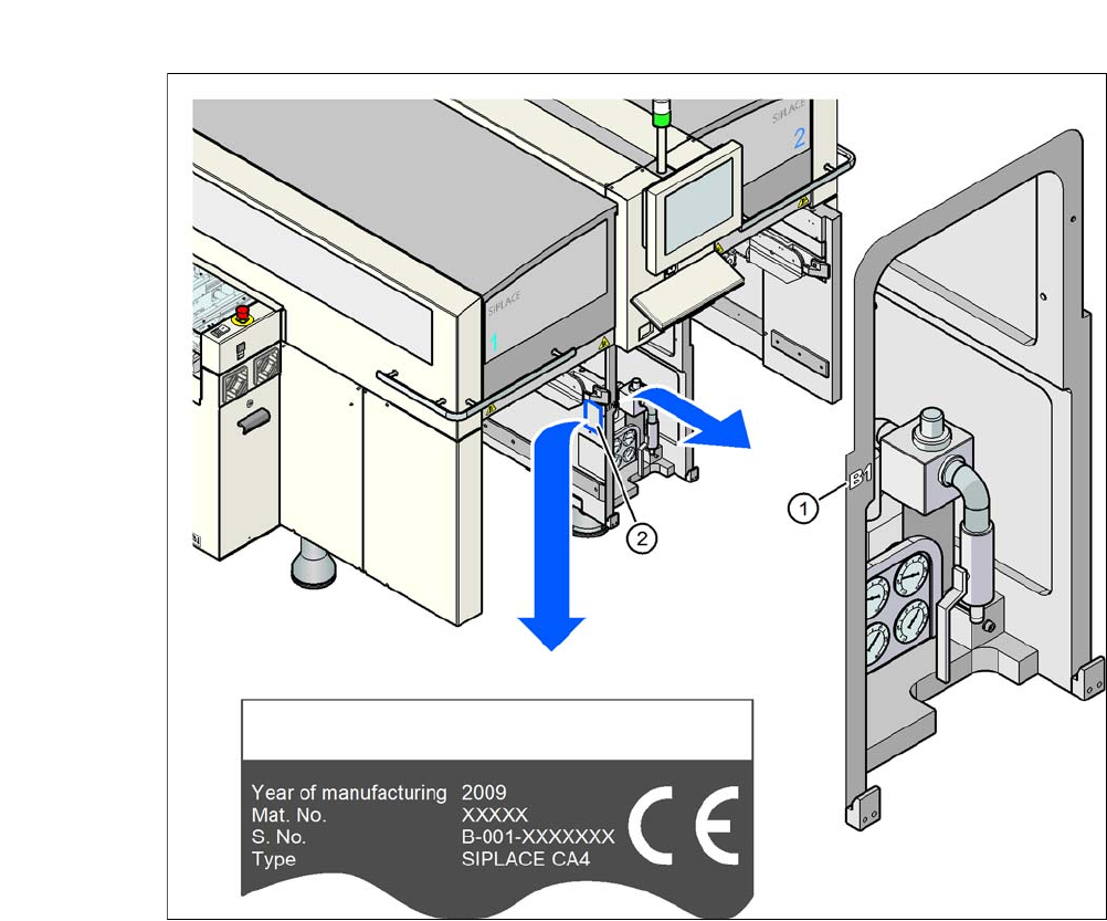
Fig. 1.1 - 2 Position of serial numbers on the placement machines
The serial number for the SIPLACE CA placement machines can be found at two locations.
– Without prefix zeros, e.g. B-1, the serial number can be found stamped onto the side of the
pneumatic unit (1), on the left side of the machine frame.
– With prefix zeros, e.g. B-001, the serial number can be found stamped onto the type plate (2).