00195941-03-UM SiplaceCA-EN.pdf - 第233页
User Manual SIPLACE CA 3 Technical Data Edition 08/2011 EN 3.14 PCB Single Conveyor 233 3.14 PCB Single Conveyor [001 19625-xx] Modular single conveyor II, 2380 mm [001 19626-xx] Fixed conveyor side right, HF /X/CA/D ser…

3 Technical Data User Manual SIPLACE CA
3.13 Vision Cameras Edition 08/2011 EN
232
3.13.6.4 Inkdot-Criteria
3
Methods - Synthetic fiducial recognition method
- Mean grayscale value
- Histogram method
- Template matching
Shapes and sizes of fiducials/
structures for
Synthetic fiducials
Other methods
For dimensions of synthetic fiducials, see Section 3.13.6.3
Fidu-
cial-Criteria
Min. 0.3 mm
Max. 5 mm
Masking material Good coverage
Detection time Depends on the method: 20 ms - 0.2s
User Manual SIPLACE CA 3 Technical Data
Edition 08/2011 EN 3.14 PCB Single Conveyor
233
3.14 PCB Single Conveyor
[00119625-xx] Modular single conveyor II, 2380 mm
[00119626-xx] Fixed conveyor side right, HF/X/CA/D series
[00119628-xx] Fixed conveyor side left, HF/X/CA/D series
[00119629-xx] Conveyor width 250/508 mm, HF/X/CA series
In its standard version, the placement machine is equipped with a PCB single conveyor. The PCB
dual conveyor is available as an option ex factory (see section 3.15
, page 238). The left or the
right side of the PCB conveyor can be used as the stationary side, as required.
The conveyor belts are driven by DC motors. There is a lifting table for clamping the PCBs in each
processing area. The PCB conveyor width can either be set from the user interface or preset in
the placement program.
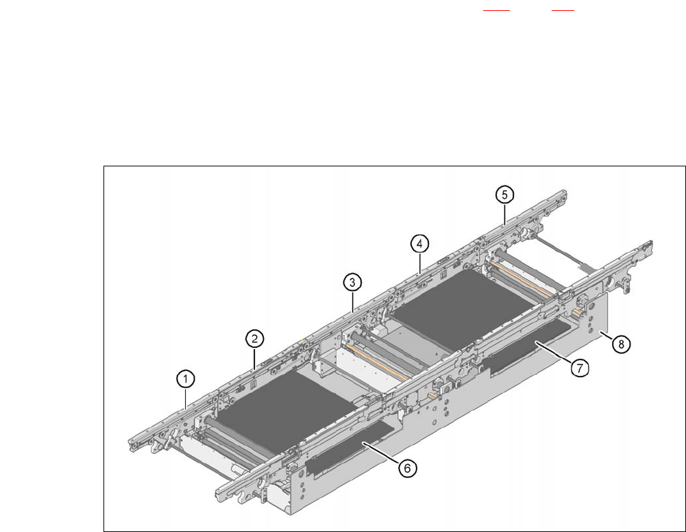
3.14.1 Structure
3
Fig. 3.14 - 1 Structure of the PCB single conveyor
(1) Input conveyor (2) Processing conveyor 1
(3) Intermediate conveyor (4) Processing conveyor 2
(5) Output conveyor (6) Lifting table 1
(7) Lifting table 2 (8) Assembly tub

3 Technical Data User Manual SIPLACE CA
3.14 PCB Single Conveyor Edition 08/2011 EN
234
3.14.2 Technical Data
3
3
Fixed conveyor side Right or left
PCB dimensions
Standard (length x width)
Configuration "Width PCB"
Configuration "Conveyor width 21"
Long board option
a
Long board option and Wide board
configuration
50 mm x 50 mm to 450 mm x 460 mm
b
50 mm x 50 mm to 450 mm x 508 mm
b
50 mm x 50 mm to 450 mm x 533 mm
b
50 mm x 80 mm to 610 mm x 460 mm
b
50 mm x 80 mm to 610 mm x 508 mm
b
PCB thickness
Standard 0.3 mm to 4.5 mm ± 0.2 mm
(thicker PCBs on request)
Vacuum tooling on request
Thin PCBs on a carrier
PCB warpage see section 3.14.4
, page 235
PCB weight Up to 3 kg
Clearance on PCB underside
Standard
Option
25 mm ± 0.2 mm
max. 40 mm ± 0.2 mm
Component-free PCB handling edge 3 mm
PCB changeover time < 2.5 s
PCB positioning accuracy ± 0.5 mm
PCB transport height 830mm ± 15mm (standard)
900mm ± 15mm (optional)
930mm ± 15mm (optional)
950mm ± 15mm (SMEMA: optional)
Type of interface SMEMA / Siemens
Bad fiducial detection possible
Automatic width adjustment possible
a) See option "Long board", section 7.9, page 473
b) With PCB widths > 450 mm make sure that the peripheral modules are also able to process these widths.