00195941-03-UM SiplaceCA-EN.pdf - 第238页
3 Technical Data User Manual SIPLACE CA 3.15 Flexible Dual PCB Conveyor Edition 08/2011 EN 238 3.15 Flexible Dual PCB Conveyor [001 19627-xx] Modular dual con veyor II, 2380 mm [001 19626-xx] Fixed co nveyor side right, …
User Manual SIPLACE CA 3 Technical Data
Edition 08/2011 EN 3.14 PCB Single Conveyor
237
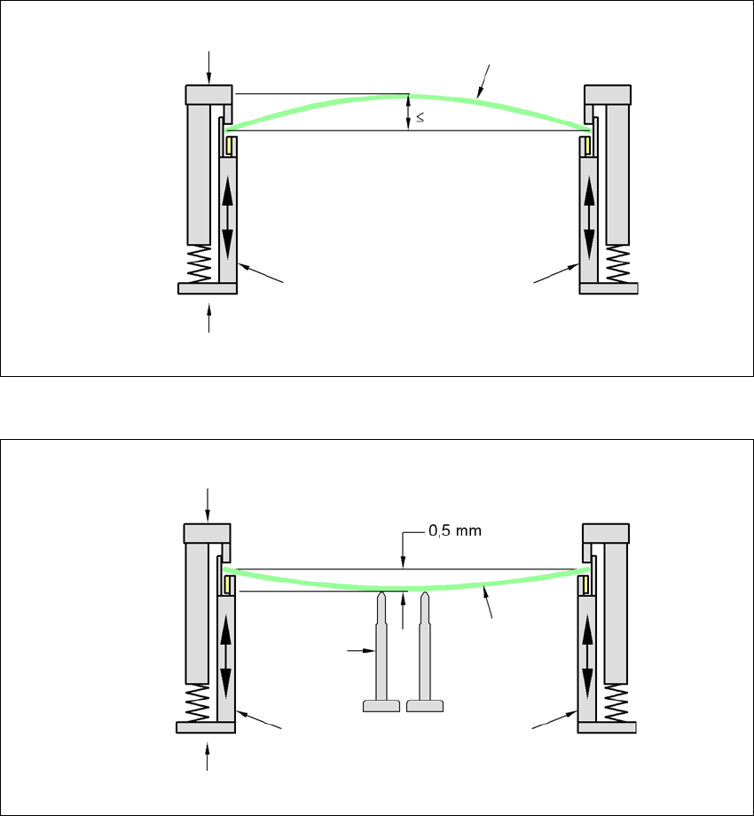
3.14.4.2 PCB-Warpage during Placement
In case of a warpage of 0,5 mm problems can occur during focusing of local fiducials and inkdots
in the PCB-center. The digital camera's focus is 2 mm. When all the tolerances are taken into ac-
count, this value is reduced to 1.5 mm. Also note that the component height is reduced by the war-
page.
3
3
PCB warpage down, max. 0.5 mm
3
Use magnetic pin supports to achieve this value.
Movable clamping device
Fixed clamped edge
Printed circuit board
conveyor side
0.5 mm
Printed circuit board
Magnetic pin
support
Movable clamping device
Fixed clamped edge
Conveyor side
3 Technical Data User Manual SIPLACE CA
3.15 Flexible Dual PCB Conveyor Edition 08/2011 EN
238
3.15 Flexible Dual PCB Conveyor
[00119627-xx] Modular dual conveyor II, 2380 mm
[00119626-xx] Fixed conveyor side right, HF/X/CA/D series
[00119628-xx] Fixed conveyor side left, HF/X/CA/D series
[00119929-xx] Conveyor width 250 / 508 mm, HF/X/CA series
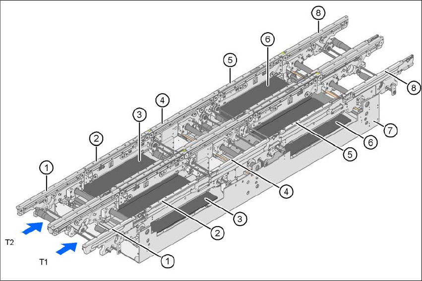
3.15.1 Structure
3
Fig. 3.15 - 1 Structure of the PCB dual conveyor
(1) Input conveyor
(2) Processing conveyor 1
(3) Lifting table 1
(4) Intermediate conveyor
(5) Processing conveyor 2
(6) Lifting table 2
(7) Assembly tub
(8) Output conveyor
T1 Conveyor track 1
T2 Conveyor track 2
User Manual SIPLACE CA 3 Technical Data
Edition 08/2011 EN 3.15 Flexible Dual PCB Conveyor
239
3.15.2 Technical Data
3
Fixed conveyor side Right or left
PCB format
Standard (length x width)
Wide board configuration
Long board option
a
Long board option in Wide board
"configuration
Dual conveyor in Single conveyor mode
Standard (length x width)
Wide board configuration
Long board option
Long board option in Wide board
configuration
a) See option "Long board", section 7.9, page 473
50 mm x 50 mm to 450 mm x 216 mm
50 mm x 50 mm to 450 mm x 250 mm
50 mm x 80 mm to 610 mm x 216 mm
50 mm x 80 mm to 610 mm x 250 mm
50 mm x 50 mm to 450 mm x 380 mm
50 mm x 50 mm to 450 mm x 450 mm
50 mm x 80 mm to 610 mm x 380 mm
50 mm x 80 mm to 610 mm x 450 mm
PCB thickness
Standard 0.3 mm to 4.5 mm ± 0.2 mm
(thicker PCBs on request)
Vacuum tooling on request
Thin PCBs on a carrier
PCB warpage see section 3.14.4
, page 235
PCB weight Up to 3 kg
Clearance on PCB underside
Standard
Option
25 mm ± 0.2 mm
max. 40 mm ± 0.2 mm
PCB transport height 830mm ± 15mm (standard)
900mm ± 15mm (optional)
930mm ± 15mm (optional)
950mm ± 15mm (SMEMA: optional)
Type of interface SMEMA / Siemens
Component-free PCB handling edge 3 mm
PCB changeover time < 2.5 s
PCB positioning accuracy ± 0.5 mm
Conveyor mode synchronous or asynchronous
Placement contents per conveyor type same or different
PCB width for each type of conveyor same or different
Bad fiducial detection synchronous: possible, no global fiducials
asynchronous: possible
Automatic width adjustment synchronous: possible, asynchronous: possible