00195941-03-UM SiplaceCA-EN.pdf - 第246页
4 Setting Up and Commissioning User Manual SIPLACE CA 4.2 Delivery Configuration and Transportati on of Placement Machine Edition 08/2011 EN 246 4.2.1.2 Weight of Placem ent Machine When Ready for Delivery The following …
User Manual SIPLACE CA 4 Setting Up and Commissioning
Edition 08/2011 EN 4.1 Dimensions and Weight
245
4 Setting Up and Commissioning
4.1 Dimensions and Weight
The dimensions and weight of the placement machine can be found in section 3.4, page 127.
4.2 Delivery Configuration and Transportation of
Placement Machine
4.2.1 Transportation Packaging
Within Europe the placement machine is transported on a wooden pallet and is wrapped in plastic
foil. Outside Europe, the machine is supplied in a wooden crate mounted on a stable wooden pal-
let.
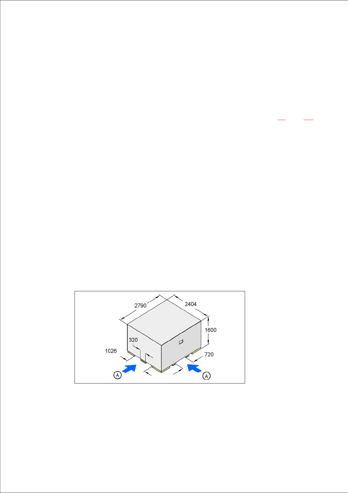
4.2.1.1 Dimensions of Transportation Packaging
The dimension of the wooden transport crate are as follows:
Length 2404 mm
Width 2790 mm
Height 1600 mm 4
4
Fig. 4.2 - 1 Transport crate - dimension in millimeters
(A) Fork-lift attachment points

4 Setting Up and Commissioning User Manual SIPLACE CA
4.2 Delivery Configuration and Transportation of Placement Machine Edition 08/2011 EN
246
4.2.1.2 Weight of Placement Machine When Ready for Delivery
The following table contains the weight of the placement machine when ready for delivery.
4
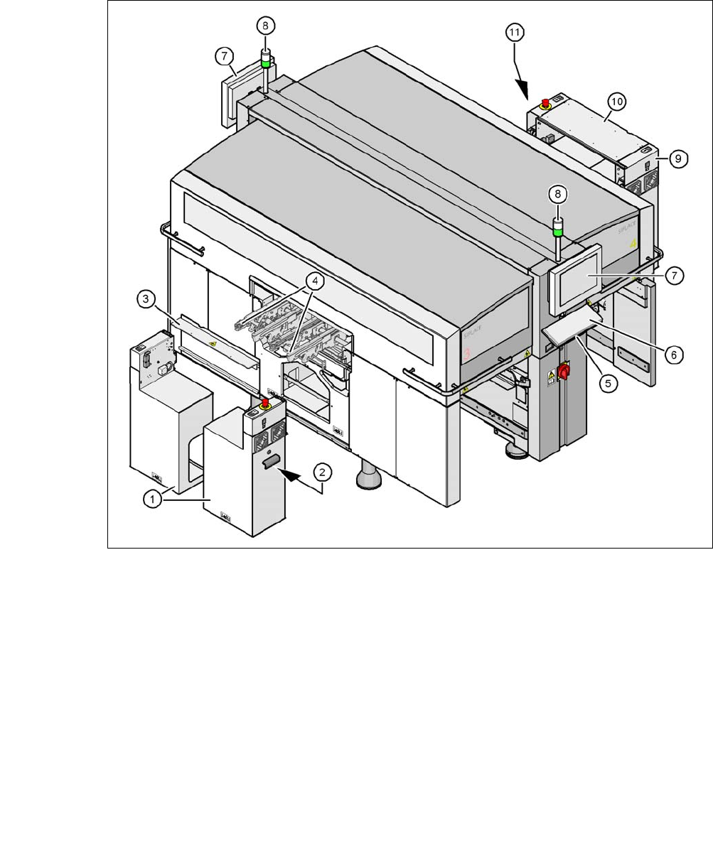
4.2.2 Delivery Configuration
The placement machine is delivered with the following configuration:
– The extension kit on the PCB output side (item 1 in fig. 4.2 - 2
) is dismantled and has been
removed from the machine.
– The axis unit (item 2 in fig. 4.2 - 2
) in the extension kit on the PCB output side is placed on a
transportation cushion. All cables are attached to the axis unit.
– The track on the single conveyor is set to a width of 210 mm. On the dual conveyor, the width
of conveyor track 1 is 100 mm and of conveyor track 2 is 210 mm. This width setting is sig-
nificant for fine adjustment of the placement machine.
On the dual conveyor, the electrical plug-in connectors for the conveyor motor and light bar-
rier on the left-hand conveyor track are easily accessible and there is still enough space to fit
the output conveyor.
– The output conveyors (item 4 in fig. 4.2 - 2
) of the single and dual conveyors have been dis-
mantled. The electrical cables to the conveyor motors and light barriers are disconnected.
– Both keyboards (item 6 in fig. 4.2 - 2
) have been disconnected.
– The supporting plates for the keyboards (item 5 in fig. 4.2 - 2
) have been unhooked.
– Both monitors (item 7 in fig. 4.2 - 2
) have been dismantled.
– Both main malfunction displays (item 8 in fig. 4.2 - 2
) have been dismantled.
– All the gantry axes are fixed with shipping braces.
Placement
machin
Dispatch within Europe Dispatch overseas
CA3 3980 kg 4420 kg
CA4 4004 kg 4504 kg
User Manual SIPLACE CA 4 Setting Up and Commissioning
Edition 08/2011 EN 4.2 Delivery Configuration and Transportation of Placement Machine
247
4
Fig. 4.2 - 2 Delivery configuration of placement machine
(1) Extension kit at the PCB-output side - delivered disassembled and dismounted
(2) Axis unit on the PCB output side - CA4: Gantry 2 and 3, CA3: Gantry 3
(3) Transport cover
(4) Output conveyor
(5) Keyboard supporting plate
(6) Keyboard
(7) Monitor
(8) Main fault indicator
(9) Computer unit on the PCB input side
(10)Extension kit at the PCB input side - can be disassembled if necessary
(11) Axis unit at the PCB - input side - CA4 and CA3: gantries 1 and 4