00195941-03-UM SiplaceCA-EN.pdf - 第25页
User Manual SIPLACE CA 1 Introduction Edition 08/2011 EN 1.2 Description of the SIPLACE Wafer System (S WS) 25 1.2 Description of the SIPLACE W afer System (SWS) 1.2.1 Description and Pr inciple of Function Up to four SI…
1 Introduction User Manual SIPLACE CA
1.1 Machine Description Edition 08/2011 EN
24
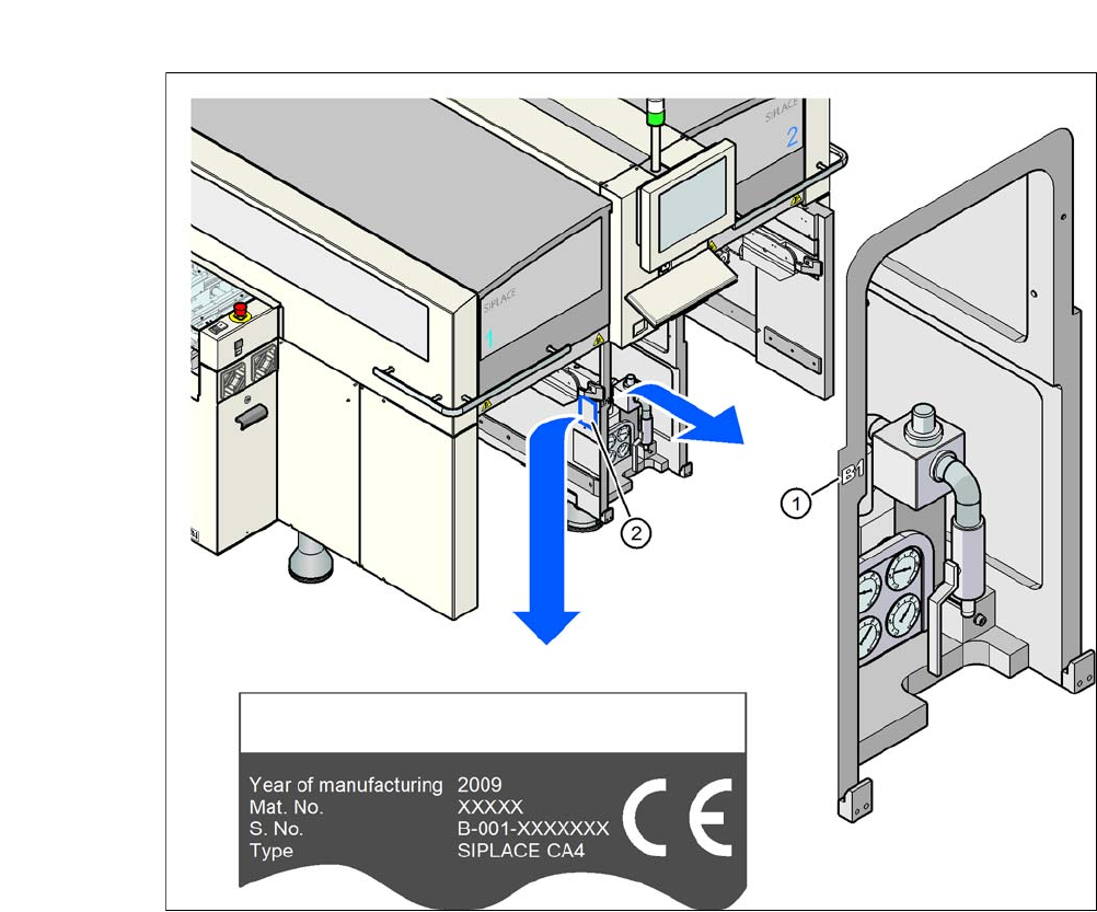
1.1.5 Serial Number of the SIPLACE CA-Placement Machine
1
Fig. 1.1 - 2 Position of serial numbers on the placement machines
The serial number for the SIPLACE CA placement machines can be found at two locations.
– Without prefix zeros, e.g. B-1, the serial number can be found stamped onto the side of the
pneumatic unit (1), on the left side of the machine frame.
– With prefix zeros, e.g. B-001, the serial number can be found stamped onto the type plate (2).

User Manual SIPLACE CA 1 Introduction
Edition 08/2011 EN 1.2 Description of the SIPLACE Wafer System (SWS)
25
1.2 Description of the SIPLACE Wafer System (SWS)
1.2.1 Description and Principle of Function
Up to four SIPLACE Wafer Systems (SWS) can be used at the SIPLACE CA placement machines.
The SWS provides the placement head with components directly from the wafer. The SWS there-
fore extends the component spectrum of the established SIPLACE X machines, by enabling
placement of bare dies from wafers.
The wafers are automatically supplied from the wafer magazine and the components can be pro-
cessed in the known placement methods.
Flip chip process - function
The wafer is automatically transported from the wafer magazine on the wafer table. This then po-
sitions the die concerned over the ejection system, which releases the die from the wafer foil. After
this release procedure, the flip unit nozzle takes the die, rotates it by 180° and makes it available
to the placement head for pickup.
The process spectrum is supplemented by the following options:
– Die attach unit:
The die attach unit takes the die from the flip unit nozzle and turns it, so that it has the same
top-bottom orientation on the board as it had on the wafer.
– Linear Dipping Unit
The Linear Dipping Unit distributes precise layers of flux for the flip chip process. After taking
over from the flip unit the placement head dips the die in to the flux layer.

1 Introduction User Manual SIPLACE CA
1.3 General Edition 08/2011 EN
26
1.2.2 Configuration Options of the SWS
The SWS can be integrated into all 4 locations.
NOTE 1
there are two different variants of the SWS. The first variant can be installed at the locations 2
and 4, the second at the locations 1 and 3.
1.3 General
1.3.1 How to Get Information
If you have questions regarding this manual or if you need further inormation on specific topics,
please contact your supervising SIPLACE-branch or us directly at:
ASM GmbH & Co. KG
Rupert-Mayer-Str. 44
D-81379 München 1
SIPLACE customer hotline: (0049) 089 20800 48642 1
E-mail: hotline.siplace@SIPLACE.com. 1