00195941-03-UM SiplaceCA-EN.pdf - 第250页
4 Setting Up and Commissioning User Manual SIPLACE CA 4.2 Delivery Configuration and Transportati on of Placement Machine Edition 08/2011 EN 250 4.2.4.3 Fork Lif t Attachment Poi nt s on the Placement Machine The next tw…

User Manual SIPLACE CA 4 Setting Up and Commissioning
Edition 08/2011 EN 4.2 Delivery Configuration and Transportation of Placement Machine
249
4.2.3.4 Fork-lift Attachment Points on the Transport Crate or Pallet
Position the fork-lift truck only at the points marked (A) in fig. 4.2 - 1. We recommend that you keep
the crate or the pallet for later use.
WARNING 4
If you do transport the placement machine without its crate or pallet, make sure you observe the
information in the next section. This will help you avoid seriously damaging the placement
machine.
4
4.2.4 Transporting the Placement Machine Without a Crate or Pallet
4.2.4.1 Safety Instructions
WARNING 4
The applicable accident prevention regulations concerning the transportation of heavy goods
must be followed.
In particular, you should wear safety boots to minimize the risk of crushing your feet.
Before transporting the machine, read this section through carefully, to avoid damaging the
placement machine.
When you are transporting the machine, make sure that all the feet are clear of the floor. If
the machine feet should drag along the floor during transportation and hit an obstacle, this
could damage the thread for the machine feet in the placement machine!
4.2.4.2 Transportation Equipment
Use a fork-lift truck with the following specification to transport the placement machine:
Fork length Min. 1800 mm
Lifting power Min. 6000 kg
Distance between forks with the forks running parallel
to the direction of PCB transport
420 mm
Distance between forks with the forks running across
the direction of PCB transport
800 mm - 900 mm

4 Setting Up and Commissioning User Manual SIPLACE CA
4.2 Delivery Configuration and Transportation of Placement Machine Edition 08/2011 EN
250
4.2.4.3 Fork Lift Attachment Points on the Placement Machine
The next two diagrams show the attachment points of the fork-lift truck forks on the placement ma-
chine, for lifting the machine off the pallet or transporting it without a pallet.
NOTE 4
When transporting the placement machine for longer distances, always use the pallet and fork-lift
truck, to avoid damaging the machine.
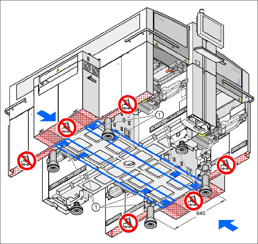
Forks parallel to the PCB conveyor 4
WARNING 4
Before lifting the placement machine, observe the following points to avoid causing irreversible
damage to the machine:
– The forks may only be opened to a degree which ensures that they are still within the area of
the machine feet (for attachment points see fig. 4.2 - 3
). The distance between the machine
feet is 776 mm. Make sure you do not increase the distance between the forks so that the
placement machine is lifted under the sides of the machine frame, as this would distort the
machine frame.
When lifting the placement machine, make sure that the forks are loaded evenly. A firm sup-
port surface between the fork and the machine prevents the machine from tipping over when
lifted. This will also prevent a one-sided load on the machine feet, which would deform the
fixing of the machine feet. We recommend that a second person monitors the lifting of the ma-
chine and ensures that the placement machine does not tip over to one side when lifted by
the fork-lift truck.
User Manual SIPLACE CA 4 Setting Up and Commissioning
Edition 08/2011 EN 4.2 Delivery Configuration and Transportation of Placement Machine
251
4
Fig. 4.2 - 3 Contact surfaces - Forks parallel to the direction of PCB transport
(1) Contact surfaces for the forks of the fork-lift