00195941-03-UM SiplaceCA-EN.pdf - 第261页
User Manual SIPLACE CA 4 Setting Up and Commissioning Edition 08/2011 EN 4.4 Infrastructure of Installation Location 261 4.4.3 Compressed Air Supply on the SWS The compressed air fed to the SWS is directly supplied via t…
4 Setting Up and Commissioning User Manual SIPLACE CA
4.4 Infrastructure of Installation Location Edition 08/2011 EN
260
4.4.2.2 Compressed Air Connection on the Placement Machine
4
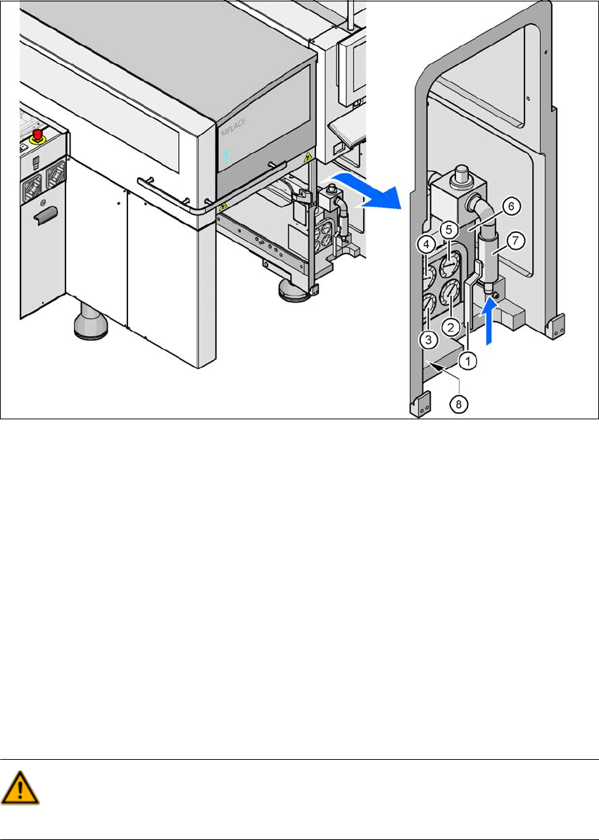
Fig. 4.4 - 1 Compressed air line connection
(1) Stop valve in the "OPEN" position
(2) Manometer for the machine component supply pressure
Target pressure: 0.5 ± 0.025 MPa, 5 ± 0.25 bar (display range 0 - 0.6 MPa, 0 - 6 bar)
(3) Manometer for the gantry distributor supply pressure
Target pressure: 0.46 ± 0.01 MPa, 4.6 ± 0.1 bar (display range 0 - 0.6 MPa, 0 - 6 bar)
(4) Manometer for the bulkcase feeder supply pressure
Target pressure: 0.25 ± 0.05 MPa, 2.5 ± 0.5 bar (display range: 0 - 0.6 MPa, 0 - 6 bar)
(5) Manometer for input pressure
Target pressure: 0.5 - 1.0 MPa, 5 - 10 bar (display range: 0 - 1.0 MPa, 0 - 10 bar)
(6) Compressed air filter
(7) Compressed air connection
(8) Hexagon socket-head screw for fixing the pneumatic unit
WARNING
NEVER detach compressed air lines while they are still pressurized. Risk of injury. 4
User Manual SIPLACE CA 4 Setting Up and Commissioning
Edition 08/2011 EN 4.4 Infrastructure of Installation Location
261
4.4.3 Compressed Air Supply on the SWS
The compressed air fed to the SWS is directly supplied via the placement machine. (See also
3.3.2
on page 125.)
4.4.4 Power Supply to the Placement Machine
4
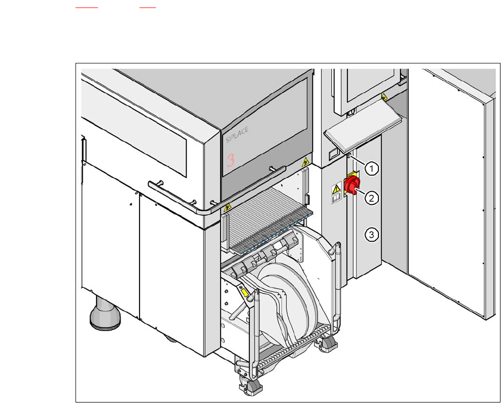
Fig. 4.4 - 2 Position of the power supply on the placement machine
4
(1) Lock
(2) Main power switch secured to prevent switching on again
(3) Cover
4 Setting Up and Commissioning User Manual SIPLACE CA
4.4 Infrastructure of Installation Location Edition 08/2011 EN
262
4.4.4.1 Hazard Warnings
WARNING
The placement machine is supplied with 3 x 208 VAC, 3 x 230 VAC, 3 x 380 VAC, 3 x 400 VAC or
3x415VAC ± 5%, 50/60Hz mains voltage. This means that some parts of the system carry po-
tentially lethal voltages - even when switched off at the main power switch. Incorrect handling of
the placement machine can therefore result in death or severe injury or considerable damage to
equipment. 4
Always follow the applicable accident prevention and DIN regulations (particularly DIN EN 60
204, part 1).
Only trained and qualified personnel may remove the cover over the power supply unit and
connect the machine to the power supply.
4
4
4.4.4.2 Checking the Power Supply
Check whether the power supply complies with the prescribed machine specifications (see table
in section 3.3
, page 125).
Note: 4
The document "Network Configuration (Electricity and Compressed Air) for SMD Systems at the
Customer Site" [00191409-xx] describes measures for achieving the required specifications.
Note: 4
For technical reasons, load peaks occur in the power supply. Please contact your electricity com-
pany to clarify the mains impedance, if necessary.
4.4.4.3 Power Supply Cable - Specification
The following specifications apply to the power supply cable:
5 x 6 mm² for 3 x 380 VAC / 3 x 400 VAC / 3 x 415 VAC
5 x 6 mm² for 3 x 208 VAC / 3 x 230 VAC
The color coding for the wires will depend on the country in which the system is operated.