00195941-03-UM SiplaceCA-EN.pdf - 第263页
User Manual SIPLACE CA 4 Setting Up and Commissioning Edition 08/2011 EN 4.4 Infrastructure of Installation Location 263 WA R N I N G 4 The electrical leads to each individual machin e an d to the options inst alled (e.g…
4 Setting Up and Commissioning User Manual SIPLACE CA
4.4 Infrastructure of Installation Location Edition 08/2011 EN
262
4.4.4.1 Hazard Warnings
WARNING
The placement machine is supplied with 3 x 208 VAC, 3 x 230 VAC, 3 x 380 VAC, 3 x 400 VAC or
3x415VAC ± 5%, 50/60Hz mains voltage. This means that some parts of the system carry po-
tentially lethal voltages - even when switched off at the main power switch. Incorrect handling of
the placement machine can therefore result in death or severe injury or considerable damage to
equipment. 4
Always follow the applicable accident prevention and DIN regulations (particularly DIN EN 60
204, part 1).
Only trained and qualified personnel may remove the cover over the power supply unit and
connect the machine to the power supply.
4
4
4.4.4.2 Checking the Power Supply
Check whether the power supply complies with the prescribed machine specifications (see table
in section 3.3
, page 125).
Note: 4
The document "Network Configuration (Electricity and Compressed Air) for SMD Systems at the
Customer Site" [00191409-xx] describes measures for achieving the required specifications.
Note: 4
For technical reasons, load peaks occur in the power supply. Please contact your electricity com-
pany to clarify the mains impedance, if necessary.
4.4.4.3 Power Supply Cable - Specification
The following specifications apply to the power supply cable:
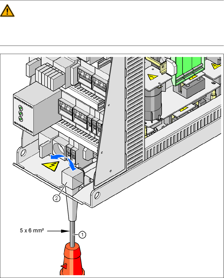
5 x 6 mm² for 3 x 380 VAC / 3 x 400 VAC / 3 x 415 VAC
5 x 6 mm² for 3 x 208 VAC / 3 x 230 VAC
The color coding for the wires will depend on the country in which the system is operated.
User Manual SIPLACE CA 4 Setting Up and Commissioning
Edition 08/2011 EN 4.4 Infrastructure of Installation Location
263
WARNING 4
The electrical leads to each individual machine and to the options installed (e.g. Productivity Lift)
must be clearly labeled and easily assignable. The regulations of the country in which the
machine is operated apply.
4
Fig. 4.4 - 3 Cross-section of the main power cable
(1) Power supply cable
(2) Angled cable gland
4 Setting Up and Commissioning User Manual SIPLACE CA
4.4 Infrastructure of Installation Location Edition 08/2011 EN
264
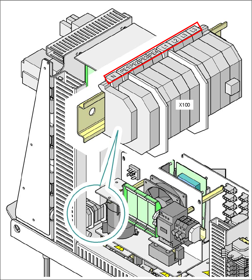
4.4.4.4 Connecting the Power Supply Cable
4
Fig. 4.4 - 4 Terminal panel for connecting the power cable
(L1) Three-phase
(L2) Three-phase
(L3) Three-phase
(N) Neutral conductor
(PE) Protective earth wires PE1, PE2, PE3, PE4
(X100) Terminal panel