00195941-03-UM SiplaceCA-EN.pdf - 第265页
User Manual SIPLACE CA 4 Setting Up and Commissioning Edition 08/2011 EN 4.4 Infrastructure of Installation Location 265 Crimp a ferrule onto each end of the wir e. Loosen the nut on the ang led cable gland (ite m 2 …
4 Setting Up and Commissioning User Manual SIPLACE CA
4.4 Infrastructure of Installation Location Edition 08/2011 EN
264
4.4.4.4 Connecting the Power Supply Cable
4
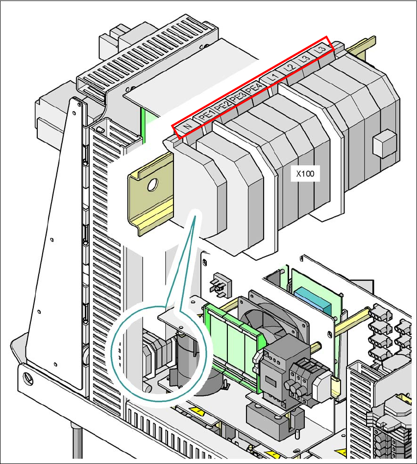
Fig. 4.4 - 4 Terminal panel for connecting the power cable
(L1) Three-phase
(L2) Three-phase
(L3) Three-phase
(N) Neutral conductor
(PE) Protective earth wires PE1, PE2, PE3, PE4
(X100) Terminal panel

User Manual SIPLACE CA 4 Setting Up and Commissioning
Edition 08/2011 EN 4.4 Infrastructure of Installation Location
265
Crimp a ferrule onto each end of the wire.
Loosen the nut on the angled cable gland (item 2 in fig. 4.4 - 3).
Fold up the angled cable gland.
Run the power supply cable through the angled cable gland and to the terminal panel X100
(see X100 in fig. 4.4 - 4
).
Connect the cable to the terminal and ensure that it has a sufficient bending radius. The wires
must not be kinked.
Close the angled cable gland (item 2 in fig. 4.4 - 3) and manually tighten the nut.
4 Setting Up and Commissioning User Manual SIPLACE CA
4.4 Infrastructure of Installation Location Edition 08/2011 EN
266
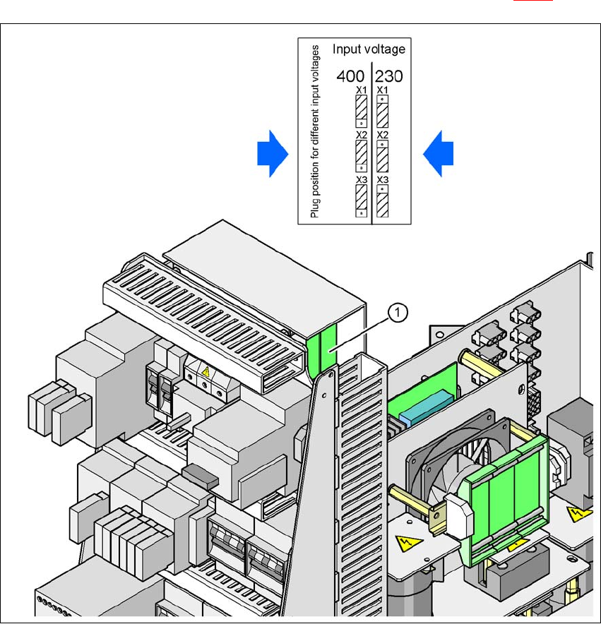
4.4.4.5 Checking the Inrush Current Limitation Jumpers
The inrush current limitation must be configured in relation to the supply voltage. This is achieved
with the help of plug-in bridges on the inrush current limitation board (item 1 in fig. 4.4 - 5
).
4
Fig. 4.4 - 5 Position of the board and connectors for the inrush current limitation
4
(1) Inrush current limitation board
X1, X2, X3 Connectors for configuring the inrush current limitation on the board
Check the jumper assignment and correct if necessary.
3 x 380 VAC
3 x 400 VAC
3 x 415 VAC
3 x 208 VAC
3 x 230 VAC