00195941-03-UM SiplaceCA-EN.pdf - 第268页
4 Setting Up and Commissioning User Manual SIPLACE CA 4.5 Setting Up the Placement Machine Edition 08/2011 EN 268 4.5.3 T ools and Equipment Y ou will need the following tools and equipment to adjust the height of the pl…

User Manual SIPLACE CA 4 Setting Up and Commissioning
Edition 08/2011 EN 4.5 Setting Up the Placement Machine
267
4.5 Setting Up the Placement Machine
4.5.1 PCB Conveyor Height for Placement Machine
The placement machine can be set to accommodate the following PCB conveyor heights:
830 mm ± 15 mm (standard height) 4
900 mm ± 15 mm 4
930 mm ± 15 mm 4
950 mm ± 15 mm (SMEMA height) 4
NOTE 4
The PCB conveyor height is the distance between the top edge of the PCB conveyor belt and the
bottom edge of the machine feet.
4.5.2 Warning Instructions
DANGER 4
Only ASM-technicians or certified persons may set up and start up the machine.
Always follow the applicable accident prevention regulations.
When fitting the machine feet, never lie down under the placement machine. All the modules
and parts can be fitted from the spaces for the component feeder tables. If you still need to
perform assembly work to the underside of the placement machine, take appropriate mea-
sures to secure the machine first. The fork-lift truck alone is not a suitable support!
Make sure that the gantries are positioned over the PCB conveyor area so that you do not
restrict your head movement during assembly, thus excluding the risk of injury.
You require two people to set the height of the placement machine:
– One person carries out the required assembly work.
– The other person monitors the stability of the lifted machine during assembly.
Wear special safety boots to protect your feet. Each machine foot weighs 6.75 kg.

4 Setting Up and Commissioning User Manual SIPLACE CA
4.5 Setting Up the Placement Machine Edition 08/2011 EN
268
4.5.3 Tools and Equipment
You will need the following tools and equipment to adjust the height of the placement machine:
– Open-ended wrench SW 36 [00096286-01]
Size 36 for the adjusting screw M24x2x120 to adjust the height of the machine feet 4
– Hook wrench 135 - 145 for adjusting the middle machine foot [00376519-xx]
– Single-ended spanner SW 65 [00353827-01]
Size 65 for the hexagon lock nut M24 on the middle machine foot 4
– Allen key, size 10 [00373926-01]
for hexagon socket head screws M12x80 for fixing the spacers for the middle machine feet4
– Allen key, size 19 [00373928-01]
for hexagon socket head screw M24x90 for temporarily clamping the four outer machine
feet clamps 4
– Torque wrench with hexagonal pin, size 19, tightening torque 130 Nm
for permanently fitting the four outer machine feet
– Fork-lift truck
Fork length: Min. 1800 mm 4
Carrying power: Min. 6000 kg 4
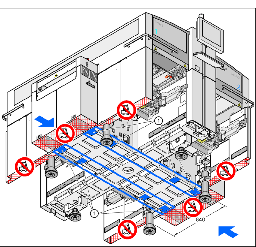
Width between forks: see fig. 4.5 - 1
4
– Spirit level: accuracy 0.02 mm/m
– Air cushion transport system: SIPLACE HSxx [00119002-xx]
User Manual SIPLACE CA 4 Setting Up and Commissioning
Edition 08/2011 EN 4.5 Setting Up the Placement Machine
269
4.5.4 Presetting the PCB Conveyor Height
Insert the forks of the fork-lift truck under the placement machine, as shown in fig. 4.5 - 1.
4
Fig. 4.5 - 1 Contact surfaces - Forks parallel to the direction of PCB transport
(1) Contact surfaces for the forks of the fork-lift