00195941-03-UM SiplaceCA-EN.pdf - 第272页
4 Setting Up and Commissioning User Manual SIPLACE CA 4.5 Setting Up the Placement Machine Edition 08/2011 EN 272 4 Fig. 4.5 - 3 Placement machine feet 4 (1) Outer machine foot, 4 x, 2 versio ns (see fig. 4.5 - 2 , page …
User Manual SIPLACE CA 4 Setting Up and Commissioning
Edition 08/2011 EN 4.5 Setting Up the Placement Machine
271
4
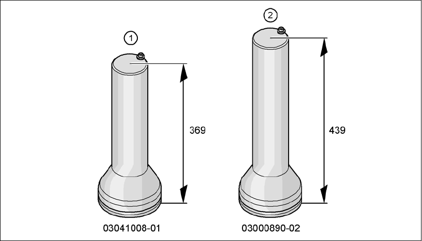
Fig. 4.5 - 2 Outer machine feet - two versions (dimensions in millimeters)
4 Setting Up and Commissioning User Manual SIPLACE CA
4.5 Setting Up the Placement Machine Edition 08/2011 EN
272
4
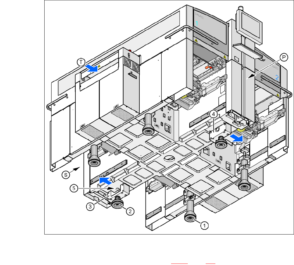
Fig. 4.5 - 3 Placement machine feet
4
(1) Outer machine foot, 4 x, 2 versions (see fig. 4.5 - 2, page 271)
(2) Middle machine foot, 2 x
(3) Spacer on the side of the power supply unit
(4) Spacer on the side of the pneumatic unit
(5) Threaded hole for the middle machine foot
(T) Direction of PCB transport
(P) Pneumatic unit
(S) Power supply unit
User Manual SIPLACE CA 4 Setting Up and Commissioning
Edition 08/2011 EN 4.5 Setting Up the Placement Machine
273
4.5.4.1 Preadjust the Height of the Middle Machine Feet
The middle machine feet are preset first. Depending on the placement machine height, you may
need to screw the spacer to the underside of the machine.
Setting the PCB conveyor height to 830 mm 4
You will not need a spacer for a PCB conveyor height of 830 mm.
Screw the middle machine foot into the threaded hole provided - as far in as possible (see
item 5 in fig. 4.5 - 3
, page 272).
Setting the PCB conveyor height to 900 mm 4
You will need the spacer for a PCB conveyor height of 900 mm.
Align the spacer so that the 90 mm side is vertical and the hole for the middle machine foot
points downwards.
4
4
4
4
4
4
4
4
4
4
4
4
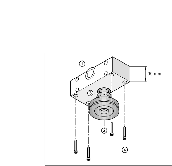
Fig. 4.5 - 4 Alignment of the spacer for a conveyor height of 900 mm
4
(1) Spacer height 90 mm
(2) Middle machine foot
(3) M24 lock nut
(4) Hexagon socket head screw M12x80, 4x