00195941-03-UM SiplaceCA-EN.pdf - 第277页
User Manual SIPLACE CA 4 Setting Up and Commissioning Edition 08/2011 EN 4.5 Setting Up the Placement Machine 277 4.5.5 Fitting the Extension Kit s to the Machine Frame 4.5.5.1 Inst all Extension Kit on the PCB Output Si…

4 Setting Up and Commissioning User Manual SIPLACE CA
4.5 Setting Up the Placement Machine Edition 08/2011 EN
276
Carefully loosen both hexagon socket-head screws M24x90 (item 2 in fig. 4.5 - 6, page 275)
with the screwdriver bit (wrench size 19 mm) and let the outer machine foot (item 1 in fig. 4.5
- 6, page 275) slowly slide down to the end stop.
Insert the correct machine foot for the required PCB conveyor height.
There are two versions of the outer machine feet: 4
– Outer machine foot for PCB conveyor height 830 mm,
length 369 mm, [03041008-01] (item. 1 in fig. 4.5 - 3
, page 272)
– Outer machine foot for PCB conveyor heights 900, 930 and 950 mm,
length 439 mm, [03000890-02] (item. 2 in fig. 4.5 - 3
, page 272)
Preset the height for each of the outer machine feet.
The distance between the underside of the machine foot and the bottom edge of the machine
frame should be as follows:
Adjust the setting screw M24x2x120 (item 3 in fig. 4.5 - 6, page 275) with the open-ended
wrench SW 36 so that you achieve the distance values from the above table, for the respec-
tive conveyor height.
Carefully lower the placement machine with the fork-lift truck, until the machine feet touch the
floor evenly. A second person should check the stability of the placement machine during low-
ering. If necessary, the clamping of the outer machine feet must be loosened a bit.
Continue to carefully lower the placement machine, until the outer machine feet touch the set-
ting screws M24x2x120 (item 3 in fig. 4.5 - 6
, page 275) for height adjustment.
Make sure that the middle machine feet (see item 2 in fig. 4.5 - 3, page 272) do not touch the
floor. If necessary, screw the middle machine feet further into the placement machine or into
the spacer.
NOTE 4
The description of how to perform final placement machine adjustment can be found in sec-
tion 4.5.17, page 316.
PCB transport height Distance from underside of machine foot
to bottom edge of machine frame
830 mm 120 mm
900 mm 190 mm
930 mm 220 mm
950 mm 240 mm

User Manual SIPLACE CA 4 Setting Up and Commissioning
Edition 08/2011 EN 4.5 Setting Up the Placement Machine
277
4.5.5 Fitting the Extension Kits to the Machine Frame
4.5.5.1 Install Extension Kit on the PCB Output Side
When the placement machine is delivered, the extension kit for the PCB output side and the PCB
output conveyor are dismantled. The procedure for attaching the extension kit to the PCB output
side is as follows:
– Fitting the Output Conveyor
see section 4.5.6, page 278
– Install Extension Kit to the PCB Output Side see section 4.5.7, page 279
– Install Axis Slide In at the CA4 and CA3 see section 4.5.8, page 286
– Fitting the Main Fault Indicator see section 4.5.14, page 311
– Integrating the Placement Machine into the Line see section 4.5.16, page 313
– Final Adjustment of the Placement Machine see section 4.5.17, page 316
4.5.5.2 Install Extension Kit on the PCB Input Side
If the extension kit for the PCB input side was also dismantled for transportation purposes, you
will need to perform the following steps before you can integrate the placement machine into your
line (see section 4.5.16
, page 313):
– Fitting the Input Conveyor
see section 4.5.9, page 291
– Install Extension Kit on the PCB Input Side see section 4.5.10, page 293
– Install Box PC Slide In at the CA4 and CA3 see section 4.5.11, page 298
– Installation of the Computer Unit of the CA4 and CA3 see section 4.5.12, page 304
– Install Axis Slide In at the CA4 and CA3 see section 4.5.13, page 309
– Fitting the Main Fault Indicator see section 4.5.14, page 311
– Integrating the Placement Machine into the Line see section 4.5.16, page 313
– Final Adjustment of the Placement Machine see section 4.5.17, page 316
4 Setting Up and Commissioning User Manual SIPLACE CA
4.5 Setting Up the Placement Machine Edition 08/2011 EN
278
4.5.6 Fitting the Output Conveyor
4.5.6.1 Tools
– Allen keys, DIN 911, set
– Phillips screwdriver, size 1
4.5.6.2 Setting Up
4
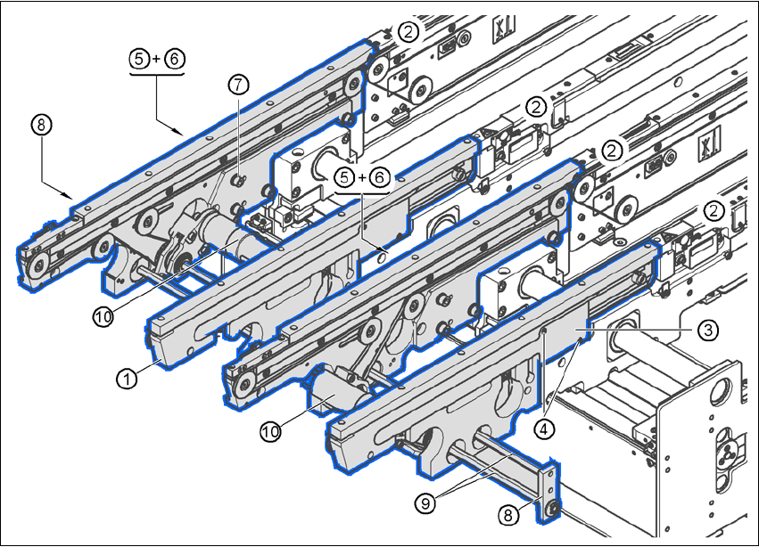
Fig. 4.5 - 7 Output conveyor - dual conveyor
(1) Side panel, output conveyor
(2) Side panel, processing conveyor 2
(3) Cable cover 20 x 200
(4) Countersunk screw, ISO 7046, M3x6, 2x per cable cover
(5) Cable cover 20 x 310
(6) Fillister head screw DIN 912, M3x5, 1x per cable cover
(7) Fillister head screw DIN 912, M6x16, and washer, 4x per panel
(8) Hexagonal shaft guidance
(9) Hexagonal shaft (single conveyor: one, dual conveyor: two)
(10)Drive unit