00195941-03-UM SiplaceCA-EN.pdf - 第278页
4 Setting Up and Commissioning User Manual SIPLACE CA 4.5 Setting Up the Placement Machine Edition 08/2011 EN 278 4.5.6 Fitting the Output Conveyor 4.5.6.1 T ools – Allen keys, DIN 91 1, set – Phillips screwdriver , size…

User Manual SIPLACE CA 4 Setting Up and Commissioning
Edition 08/2011 EN 4.5 Setting Up the Placement Machine
277
4.5.5 Fitting the Extension Kits to the Machine Frame
4.5.5.1 Install Extension Kit on the PCB Output Side
When the placement machine is delivered, the extension kit for the PCB output side and the PCB
output conveyor are dismantled. The procedure for attaching the extension kit to the PCB output
side is as follows:
– Fitting the Output Conveyor
see section 4.5.6, page 278
– Install Extension Kit to the PCB Output Side see section 4.5.7, page 279
– Install Axis Slide In at the CA4 and CA3 see section 4.5.8, page 286
– Fitting the Main Fault Indicator see section 4.5.14, page 311
– Integrating the Placement Machine into the Line see section 4.5.16, page 313
– Final Adjustment of the Placement Machine see section 4.5.17, page 316
4.5.5.2 Install Extension Kit on the PCB Input Side
If the extension kit for the PCB input side was also dismantled for transportation purposes, you
will need to perform the following steps before you can integrate the placement machine into your
line (see section 4.5.16
, page 313):
– Fitting the Input Conveyor
see section 4.5.9, page 291
– Install Extension Kit on the PCB Input Side see section 4.5.10, page 293
– Install Box PC Slide In at the CA4 and CA3 see section 4.5.11, page 298
– Installation of the Computer Unit of the CA4 and CA3 see section 4.5.12, page 304
– Install Axis Slide In at the CA4 and CA3 see section 4.5.13, page 309
– Fitting the Main Fault Indicator see section 4.5.14, page 311
– Integrating the Placement Machine into the Line see section 4.5.16, page 313
– Final Adjustment of the Placement Machine see section 4.5.17, page 316
4 Setting Up and Commissioning User Manual SIPLACE CA
4.5 Setting Up the Placement Machine Edition 08/2011 EN
278
4.5.6 Fitting the Output Conveyor
4.5.6.1 Tools
– Allen keys, DIN 911, set
– Phillips screwdriver, size 1
4.5.6.2 Setting Up
4
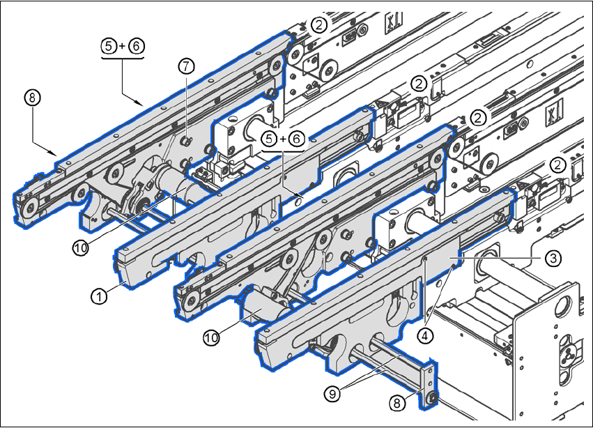
Fig. 4.5 - 7 Output conveyor - dual conveyor
(1) Side panel, output conveyor
(2) Side panel, processing conveyor 2
(3) Cable cover 20 x 200
(4) Countersunk screw, ISO 7046, M3x6, 2x per cable cover
(5) Cable cover 20 x 310
(6) Fillister head screw DIN 912, M3x5, 1x per cable cover
(7) Fillister head screw DIN 912, M6x16, and washer, 4x per panel
(8) Hexagonal shaft guidance
(9) Hexagonal shaft (single conveyor: one, dual conveyor: two)
(10)Drive unit

User Manual SIPLACE CA 4 Setting Up and Commissioning
Edition 08/2011 EN 4.5 Setting Up the Placement Machine
279
Dismantle the cable covers (item 3 and 5 in fig. 4.5 - 7) from the sides (item 1 in fig. 4.5 - 7)
of the output conveyor.
Place the side (item 1 in fig. 4.5 - 7) carefully on the side of the processing conveyor (item 2
in fig. 4.5 - 7
).
CAUTION 4
Be careful not to cut through any of the light barrier or drive motor cables.
Fasten each side with 4 fillister head screws M6x16 and the corresponding discs (item 7 in
fig. 4.5 - 7
).
Connect the power cable to the light barriers and drive motors.
Fasten the cable covers (item 3 and 5 in fig. 4.5 - 7).
Insert the hexagonal shaft (item 9 in fig. 4.5 - 7) into the drive unit (item 10 in fig. 4.5 - 7).
Make sure that the hexagonal shaft guidance (item 8 in fig. 4.5 - 7) is always pointing towards
the conveyor side on which the drive unit (item 10 in fig. 4.5 - 7
) is fixed.
4.5.7 Install Extension Kit to the PCB Output Side
4.5.7.1 Tools
– Allen keys, DIN 911, set
– Machine key