00195941-03-UM SiplaceCA-EN.pdf - 第285页
User Manual SIPLACE CA 4 Setting Up and Commissioning Edition 08/2011 EN 4.5 Setting Up the Placement Machine 285 4.5.7.7 Inst alling the Bottom Hand Guard The placement mach ines are only supplied with one bo ttom hand …
4 Setting Up and Commissioning User Manual SIPLACE CA
4.5 Setting Up the Placement Machine Edition 08/2011 EN
284
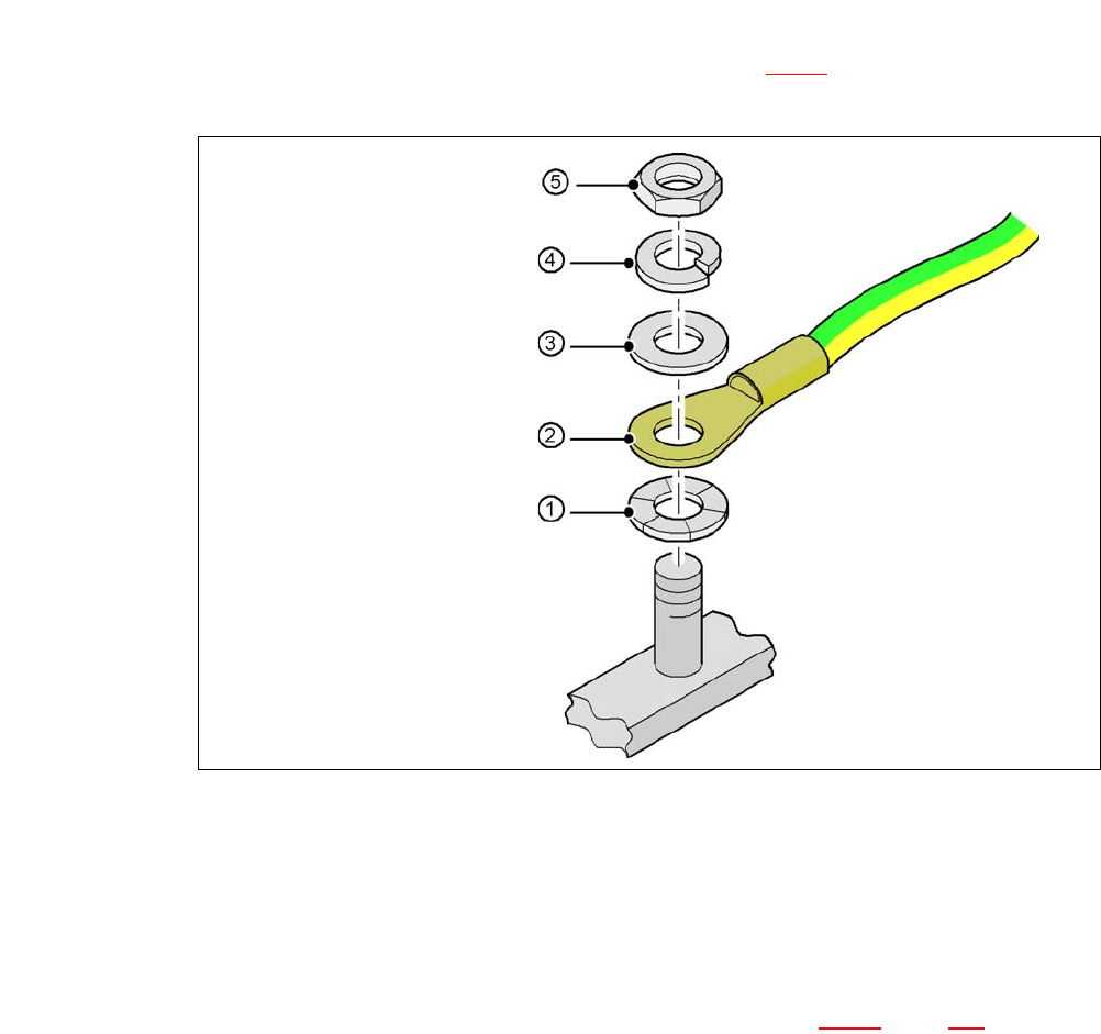
4.5.7.5 Fitting the Ground Cable for the Doors
Fasten the two ground cables for the doors (item 4 in fig. 4.5 - 8) to the machine frame as
follows:
4
Fig. 4.5 - 10 Fitting the grounding cable
4
4
4
4
4
4.5.7.6 Checking and Setting the Protective Cover Switch
Check the function of the protective cover switch (item 7 in fig. 4.5 - 9, page 282).
Adjust the protective cover switch if necessary (see Service Manual).
Hex nut M5
Spring washer M5, DIN 7980
Washer M5, DIN 125
Cable lug, annular
Contact washer
User Manual SIPLACE CA 4 Setting Up and Commissioning
Edition 08/2011 EN 4.5 Setting Up the Placement Machine
285
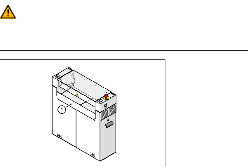
4.5.7.7 Installing the Bottom Hand Guard
The placement machines are only supplied with one bottom hand guard. However, if the place-
ment machines are installed in a line, there will be no hand guard between neighboring output and
input conveyors.
WARNING 4
Always fit the bottom hand guard at the input side of the first placement machine and on the out-
put side of the last placement machine in a line [03003432-01] with 4 hexagon socket-head
screws M4x12. This prevents unauthorized access to the inside of the machine.
4
Fig. 4.5 - 11 Fitting the "bottom" hand guard on the PCB output side
(1) Bottom hand guard [03003432-01]
4 Setting Up and Commissioning User Manual SIPLACE CA
4.5 Setting Up the Placement Machine Edition 08/2011 EN
286
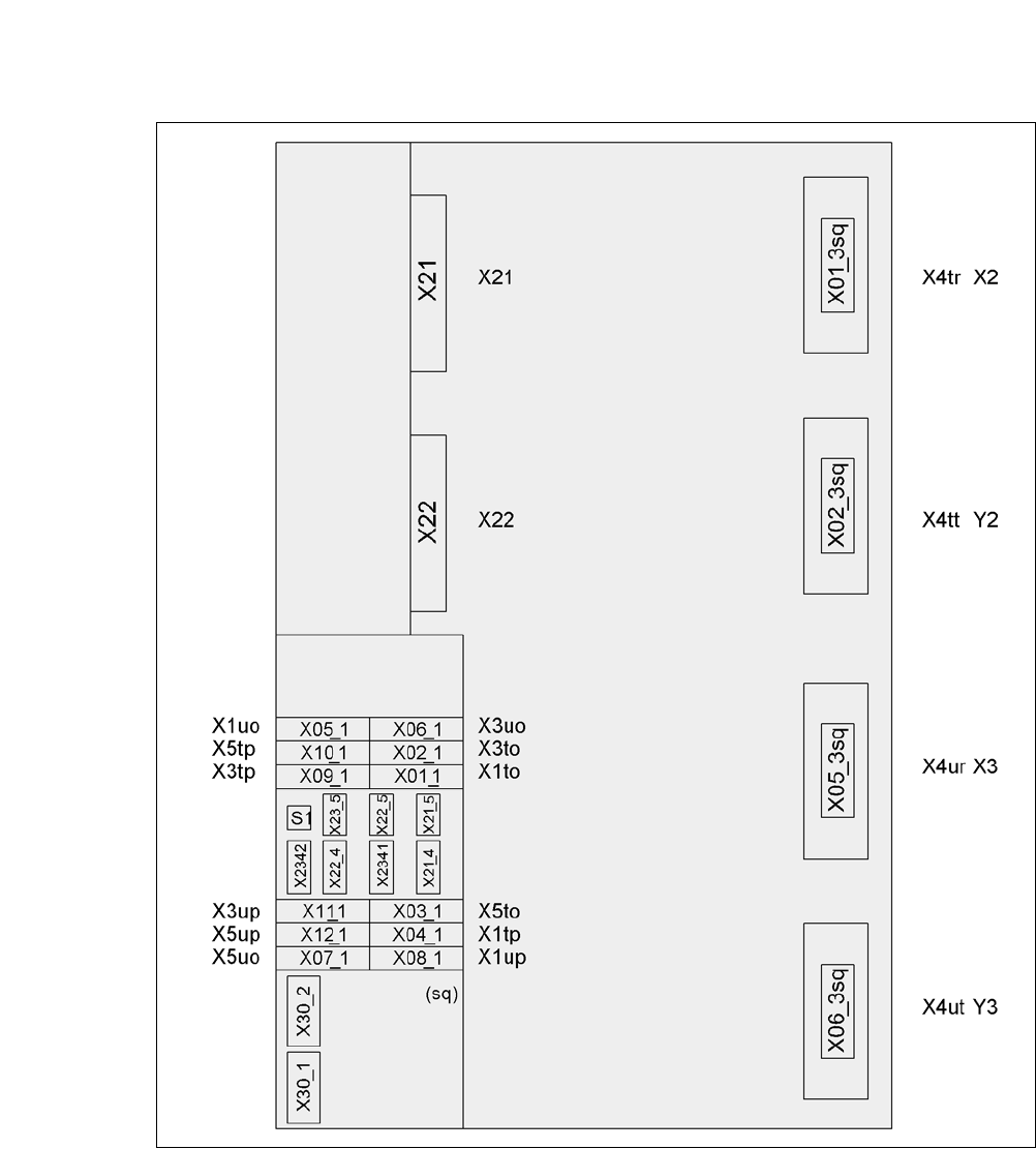
4.5.8 Install Axis Slide In at the CA4 and CA3
4.5.8.1 Axis Unit CA4 (Gantries 2 and 3) - Electrical Connection Points
4
Fig. 4.5 - 12 Axis unit CA4 (gantries 2 and 3), rear side - electrical connection points
Plug Plug
Plug