00195941-03-UM SiplaceCA-EN.pdf - 第297页
User Manual SIPLACE CA 4 Setting Up and Commissioning Edition 08/2011 EN 4.5 Setting Up the Placement Machine 297 4.5.10.5 Fitting the Ground Cable for the Doors Fasten the two ground cables for the doors (item 4 in fi…

4 Setting Up and Commissioning User Manual SIPLACE CA
4.5 Setting Up the Placement Machine Edition 08/2011 EN
296
Insert the mandrel (item 5 in fig. 4.5 - 16) for the conveyor cover into the drilling (item 6 in fig.
4.5 - 16
) on the second half of the extension kit.
Position the second half of the extension kit so that the assembly bracket lies on the assembly
bar (item 7 in fig. 4.5 - 15
).
Fasten this second half of the placement machine with 2 fillister head screws M6x16 and the
corresponding disc (item 3 in fig. 4.5 - 15
).
4.5.10.3 Fastening the Hexagonal Shaft Guidance
When using a single conveyor, fasten one guidance for the hexagonal shaft (item 8 in fig. 4.5
- 14) onto the extension kit, with two fillister head screws M6x16 and discs.
When using a dual conveyor, fasten two guidances for the hexagonal shaft (item 8 in fig. 4.5
- 14) onto the extension kit, with two fillister head screws M6x16 and discs.
4.5.10.4 Establishing Cable Connections - Extension Kit on the PCB Input Side
4
Left-hand side of the extension kit
(viewed in the direction of travel)
Connector/cable To connector/
cable
Start/Stop button
Switch, PCB conveyor cover
X61/03020410 X61/03002537
Protective cover switch, location 4
X54/03020409 X54/03002540
Button for the component trolley docking unit, loca-
tion 4
X242/03021056 X242/03021054
Right-hand side of the extension kit
(viewed in the direction of travel)
Connector/cable To connector/
cable
EMERGENCY STOP button
Start/Stop button
X64/03020687 X64/03002538
Protective cover switch, location 1
X51/03020409 X51/03002539
Button for the component trolley docking unit, loca-
tion 1
X212/03021056 X212/03021051
User Manual SIPLACE CA 4 Setting Up and Commissioning
Edition 08/2011 EN 4.5 Setting Up the Placement Machine
297
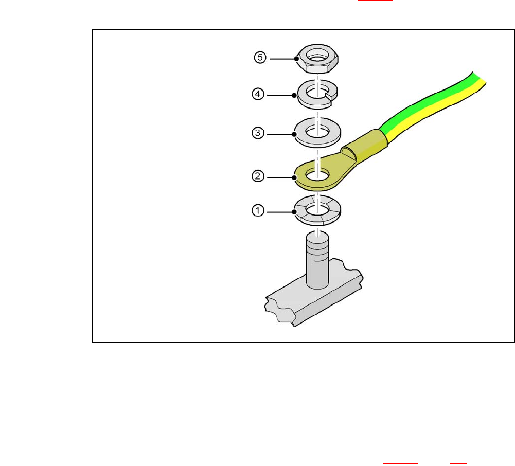
4.5.10.5 Fitting the Ground Cable for the Doors
Fasten the two ground cables for the doors (item 4 in fig. 4.5 - 15) to the machine frame as
follows:
4
Fig. 4.5 - 17 Fitting the grounding cable
4
4
4
4
4
4.5.10.6 Checking and Setting the Protective Cover Switch
Check the function of the protective cover switch (item 7 in fig. 4.5 - 16, page 282).
Adjust the protective cover switch if necessary (see Service Manual).
4
Hex nut M5
Spring washer M5, DIN 7980
Washer M5, DIN 125
Cable lug, annular
Contact washer
4 Setting Up and Commissioning User Manual SIPLACE CA
4.5 Setting Up the Placement Machine Edition 08/2011 EN
298
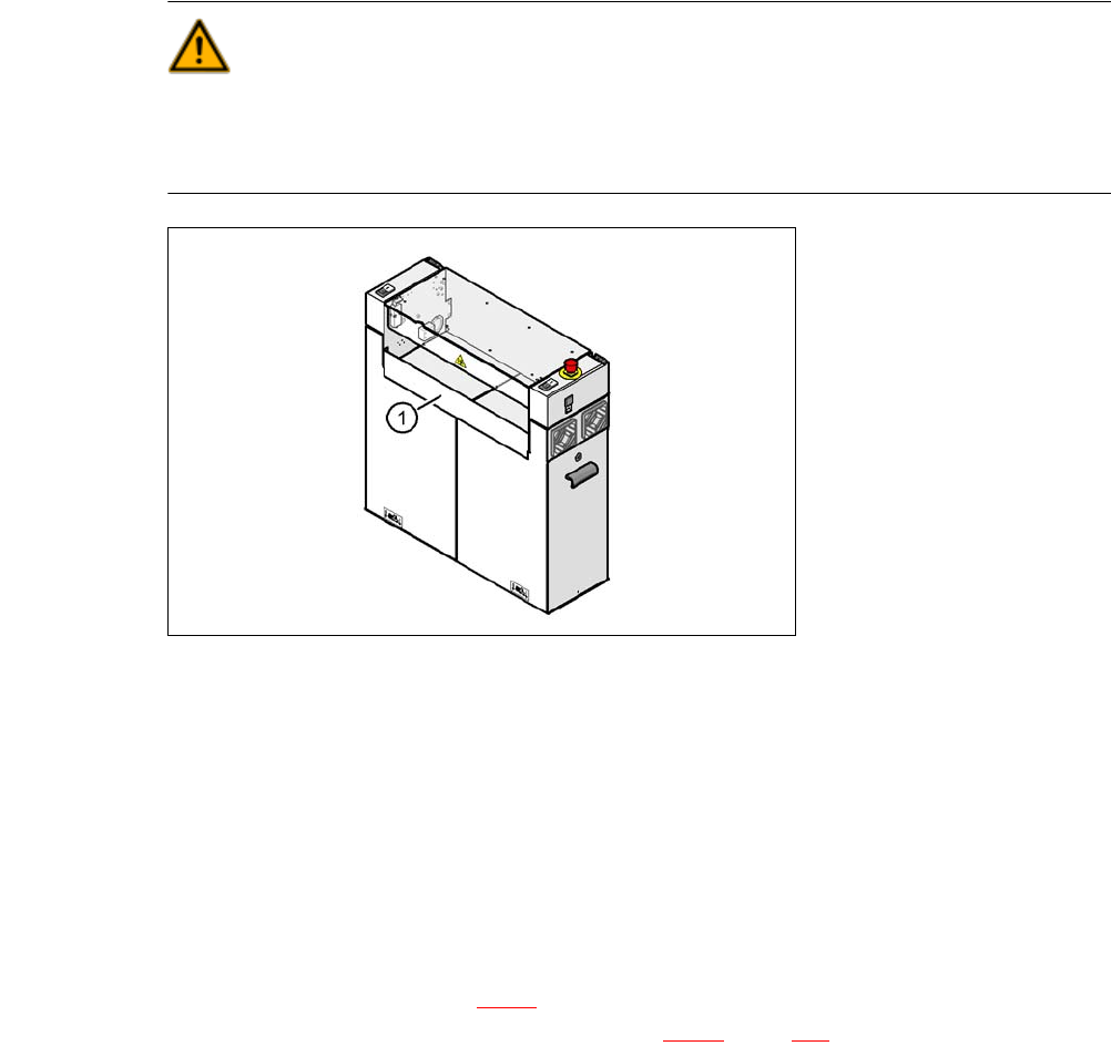
4.5.10.7 Installing the Bottom Hand Guard
The placement machines in the CA are only supplied with one bottom hand guard. However, if the
placement machines are installed in a line, there will be no hand guard between neighboring out-
put and input conveyors.
WARNING 4
Always fit the bottom hand guard at the input side of the first placement machine and on the out-
put side of the last placement machine in a line [03003432-01] with 4 hexagon socket-head
screws M4x12. This prevents unauthorized access to the inside of the machine.
4
Fig. 4.5 - 18 Fitting the "bottom" hand guard on the PCB input side
(1) Bottom hand guard [03003432-01]
4.5.11 Install Box PC Slide In at the CA4 and CA3
The placement machines of the SIPLACE CA series can either be equipped with the Box PC or
with the computer unit. Section 4.5.11
describes the installation of the Box PC. For a description
of how to install the computer unit, refer to section 4.5.12
, page 304.