00195941-03-UM SiplaceCA-EN.pdf - 第298页
4 Setting Up and Commissioning User Manual SIPLACE CA 4.5 Setting Up the Placement Machine Edition 08/2011 EN 298 4.5.10.7 Inst alling the Bottom Hand Guard The placement machin es in the CA are only supp lied with one b…
User Manual SIPLACE CA 4 Setting Up and Commissioning
Edition 08/2011 EN 4.5 Setting Up the Placement Machine
297
4.5.10.5 Fitting the Ground Cable for the Doors
Fasten the two ground cables for the doors (item 4 in fig. 4.5 - 15) to the machine frame as
follows:
4
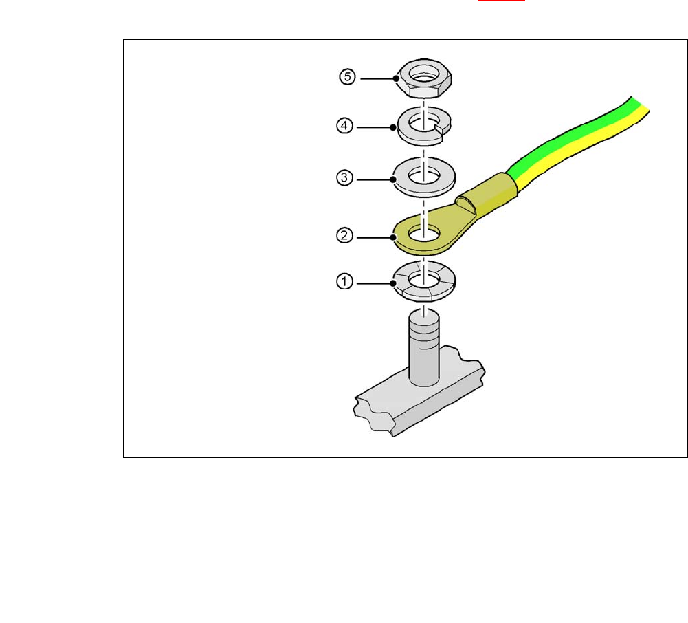
Fig. 4.5 - 17 Fitting the grounding cable
4
4
4
4
4
4.5.10.6 Checking and Setting the Protective Cover Switch
Check the function of the protective cover switch (item 7 in fig. 4.5 - 16, page 282).
Adjust the protective cover switch if necessary (see Service Manual).
4
Hex nut M5
Spring washer M5, DIN 7980
Washer M5, DIN 125
Cable lug, annular
Contact washer
4 Setting Up and Commissioning User Manual SIPLACE CA
4.5 Setting Up the Placement Machine Edition 08/2011 EN
298
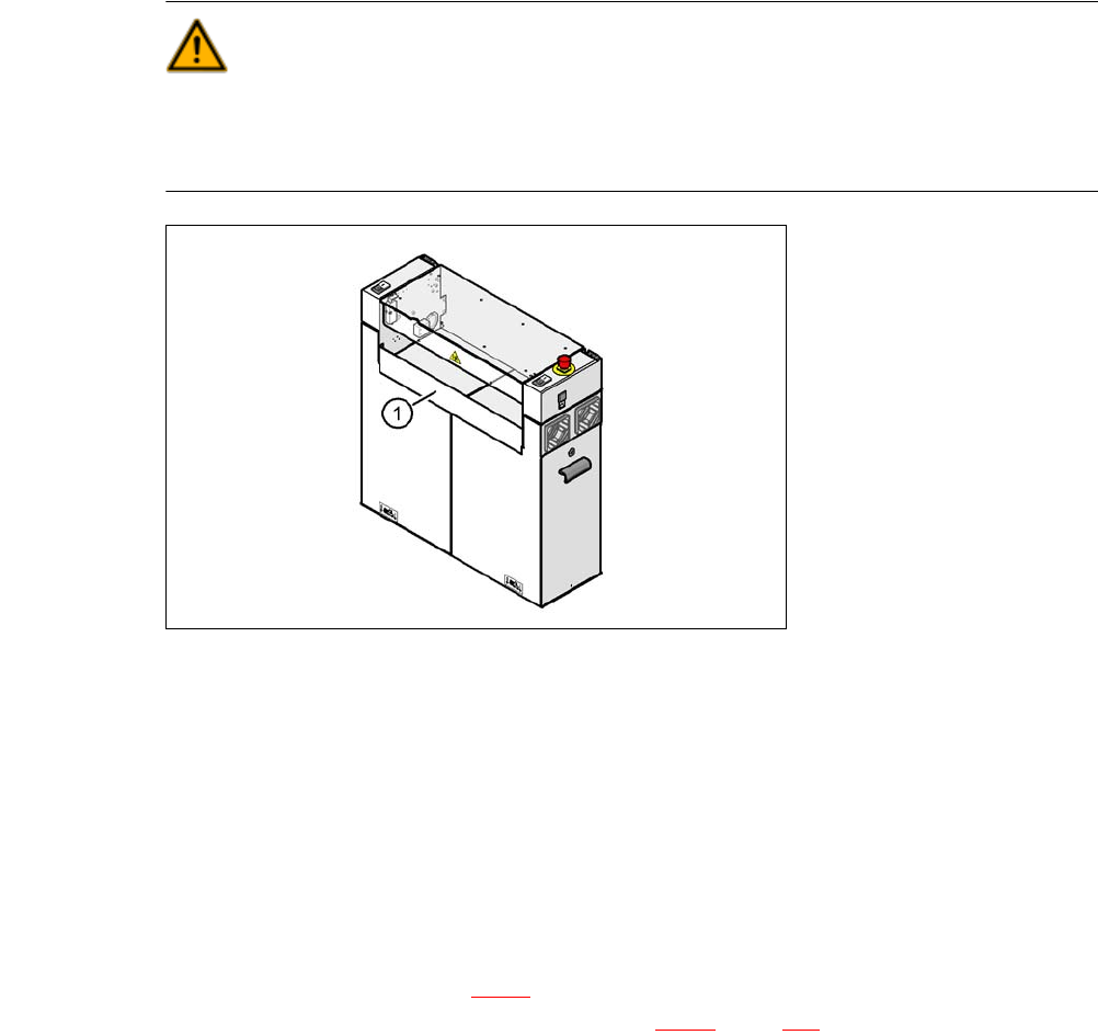
4.5.10.7 Installing the Bottom Hand Guard
The placement machines in the CA are only supplied with one bottom hand guard. However, if the
placement machines are installed in a line, there will be no hand guard between neighboring out-
put and input conveyors.
WARNING 4
Always fit the bottom hand guard at the input side of the first placement machine and on the out-
put side of the last placement machine in a line [03003432-01] with 4 hexagon socket-head
screws M4x12. This prevents unauthorized access to the inside of the machine.
4
Fig. 4.5 - 18 Fitting the "bottom" hand guard on the PCB input side
(1) Bottom hand guard [03003432-01]
4.5.11 Install Box PC Slide In at the CA4 and CA3
The placement machines of the SIPLACE CA series can either be equipped with the Box PC or
with the computer unit. Section 4.5.11
describes the installation of the Box PC. For a description
of how to install the computer unit, refer to section 4.5.12
, page 304.
User Manual SIPLACE CA 4 Setting Up and Commissioning
Edition 08/2011 EN 4.5 Setting Up the Placement Machine
299
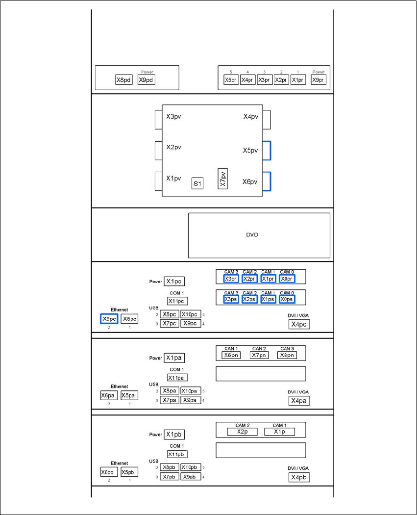
4.5.11.1 Box PC unit - Electrical Connection Points
4
Fig. 4.5 - 19 Box PC unit, front side - connecting the plugs
USB hub
Ethernet switch
(3D sensor option)
Video multiplexer
Control computer
Machine controller
3D sensor computer option